
Installation Instructions
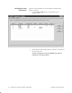
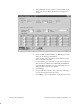
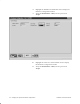
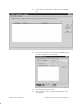
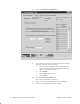
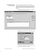
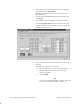
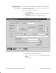
Table Of Contents
- Title page
- Contents
- About this manual
- Safety information
- Ch 1 - Introduction
- Ch 2 - Adding cards to the Controller
- Unpacking the System Controller
- Unpacking the picocells
- System Controller card configuration
- Adding cards to the System Controller (first steps)
- Jumper and DIP switch settings
- Attaching bus cables
- Adding cards to the System Controller (final steps)
- Configuring Controller cards
- Verifying the card configuration
- Ch 3 - Installing the Controller
- Ch 4 - Verifying the Controller configuration
- Ch 5 - Configuring the router
- Ch 6 - Testing picocells
- Ch 7 - Installing picocells
- Ch 8 - Connecting to external equipment
- Ch 9 - System testing
- Ch 10 - Installation inspection
- Ch 11 - Provisioning
- Ch 12 - Remote Client
- Ch 13 - Troubleshooting
- Ch 14 - Maintaining Quad T1 cards
- App A - Specifications
- App B - Standards compliance information
- App C - Part numbers
- App D - Updates and backups
- Index

1026209–0001 Revision B
Verifying the System Controller configuration 4–5
3. Select (highlight) the first Quad T1 card and double–click
on the card name to display the Hardware Configuration
window.
4. Select the Line 1, Line 2, Line 3, and Line 4 tabs, in order,
and verify the displayed information.
Select SLAVE clock reference for all line numbers except
those connected to the PBX.
For the Quad T1 port connected (or to be connected) to the
PBX, set the Clock Reference to MASTER_EXTERNAL.
A second PBX connection can be set to BACKUP. Set any
additional PBX connections to SLAVE.
5. Click Accept.
6. For each additional Quad T1 card, repeat steps 3 through 5
to verify the information for all T1 lines.
7. Click Close to return to the AROSC Configuration window.