
Installation Instructions
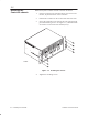
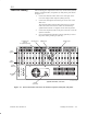
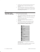
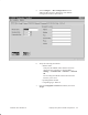
Table Of Contents
- Title page
- Contents
- About this manual
- Safety information
- Ch 1 - Introduction
- Ch 2 - Adding cards to the Controller
- Unpacking the System Controller
- Unpacking the picocells
- System Controller card configuration
- Adding cards to the System Controller (first steps)
- Jumper and DIP switch settings
- Attaching bus cables
- Adding cards to the System Controller (final steps)
- Configuring Controller cards
- Verifying the card configuration
- Ch 3 - Installing the Controller
- Ch 4 - Verifying the Controller configuration
- Ch 5 - Configuring the router
- Ch 6 - Testing picocells
- Ch 7 - Installing picocells
- Ch 8 - Connecting to external equipment
- Ch 9 - System testing
- Ch 10 - Installation inspection
- Ch 11 - Provisioning
- Ch 12 - Remote Client
- Ch 13 - Troubleshooting
- Ch 14 - Maintaining Quad T1 cards
- App A - Specifications
- App B - Standards compliance information
- App C - Part numbers
- App D - Updates and backups
- Index

1026209–0001 Revision B
Installing the Controller 3–5
After mounting the components in the rack, connect the keyboard,
monitor, touchpad cables, and printer (if used) to the ports shown
in Figure 3-3:
1. Connect the monitor video cable to the video port on the
rear of the single board computer (SBC) (slot 12).
2. Connect the touchpad to the mouse port on the rear of the
SBC card.
The touchpad and keyboard cables split off from a single
cable. The connectors on these cables are identified by
symbols that look like a computer mouse and a keyboard.
3. Connect the keyboard cable to the port on the left rear of the
System Controller.
4. If your configuration includes a printer (optional), connect
the printer to the parallel port (slot 11).
PCI
9
PCI
8
PCI
7
PCI
6
PCI
5
PCI
4
PCI
3
PCI
2
PCI
1
ISA
1
ISA
2
ISA
3
ISA
4
ISA
5
ISA
6
ISA
7
ISA
8
G-17206 F 02/14/00
COM1 port
COM1
Monitor port Mouse port
Power
connector
Keyboard
port
Power
Parallel port
(LPT1)
for optional printer
Power
indicator
Slot
number
12345678910111213
14 15 16 17 18 19 20
Slot
type ID
System Controller, rear view
Figure 3-3 System Controller connectors for monitor, keyboard, touchpad, and power
3.3
Controller cabling