
Installation Instructions
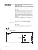
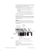
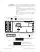
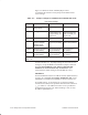
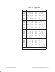
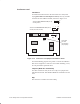
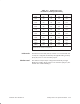
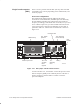
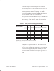
Table Of Contents
- Title page
- Contents
- About this manual
- Safety information
- Ch 1 - Introduction
- Ch 2 - Adding cards to the Controller
- Unpacking the System Controller
- Unpacking the picocells
- System Controller card configuration
- Adding cards to the System Controller (first steps)
- Jumper and DIP switch settings
- Attaching bus cables
- Adding cards to the System Controller (final steps)
- Configuring Controller cards
- Verifying the card configuration
- Ch 3 - Installing the Controller
- Ch 4 - Verifying the Controller configuration
- Ch 5 - Configuring the router
- Ch 6 - Testing picocells
- Ch 7 - Installing picocells
- Ch 8 - Connecting to external equipment
- Ch 9 - System testing
- Ch 10 - Installation inspection
- Ch 11 - Provisioning
- Ch 12 - Remote Client
- Ch 13 - Troubleshooting
- Ch 14 - Maintaining Quad T1 cards
- App A - Specifications
- App B - Standards compliance information
- App C - Part numbers
- App D - Updates and backups
- Index

1026209–0001 Revision B
Adding cards to the System Controller 2–21
To determine the proper FSB and multiplier for a particular
processor, first read the clock speed from the label on top of the
processor casing. Look at the last six numbers in the first row of
numbers and/or letters. For example, 450512 indicates a processor
clock speed (first three numbers) of 450 MHz, with 512K of
Level–2 (L2) cache (last three numbers). In general, any Pentium
II processor 333 MHz or slower uses a 66–MHz FSB, while any
processor 350 MHz or faster uses a 100–MHz FSB.
To determine the processor multiplier, divide the processor clock
speed by the FSB. For the 450–MHz processor, set the FSB to 100
MHz (SW1–1 OFF) and the multiplier at 4.5 (SW1–2 OFF,
SW1–2 ON, SW1–3 ON, and SW1–5 OFF). See the following
chart for other processor combinations and settings.
Table 2-4 SBC processor settings (switch SW1)
FSB SW1–1 X SW1–2 SW1–3 SW1–4 SW1–5
Processor (MHz)
Selects
FSB
Multiplier These switches select the multiplier.
Pentium II 233 MHz 66 ON 3.5 OFF ON OFF ON
Pentium II 266 MHz 66 ON 4 ON ON ON OFF
Pentium II 300 MHz 66 ON 4.5 OFF ON ON OFF
Pentium II 333 MHz 66 ON 5 ON ON OFF OFF
Pentium II 350 MHz 100 OFF 3.5 OFF ON OFF ON
Pentium II 400 MHz 100 OFF 4 ON ON ON OFF
Pentium II/III 450 MHz 100 OFF 4.5 OFF ON ON OFF
Pentium III 500 MHz 100 OFF 5 ON ON OFF OFF
SW1–6 to SW1–8 are reserved and should be left in the OFF position.
Highlighted (gray): Standard processor for AIReach OS Controller
Jumpers
Set all jumpers as specified in Table 2-5 . The location of each
jumper is shown in Figure 2-13.
The SBC uses the watchdog timer (jumper J17). Even though the
pre–timeout interrupt option (JP3) of the watchdog timer is not
used, leave a jumper across pins 2–3. A jumper over JP4 pins 2
and 3 enables PnP capabilities and the ability to upgrade the flash
BIOS.