
Installation Instructions
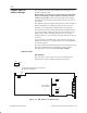
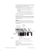
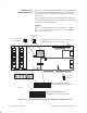
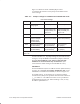
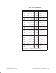
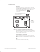
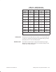
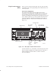
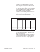
Table Of Contents
- Title page
- Contents
- About this manual
- Safety information
- Ch 1 - Introduction
- Ch 2 - Adding cards to the Controller
- Unpacking the System Controller
- Unpacking the picocells
- System Controller card configuration
- Adding cards to the System Controller (first steps)
- Jumper and DIP switch settings
- Attaching bus cables
- Adding cards to the System Controller (final steps)
- Configuring Controller cards
- Verifying the card configuration
- Ch 3 - Installing the Controller
- Ch 4 - Verifying the Controller configuration
- Ch 5 - Configuring the router
- Ch 6 - Testing picocells
- Ch 7 - Installing picocells
- Ch 8 - Connecting to external equipment
- Ch 9 - System testing
- Ch 10 - Installation inspection
- Ch 11 - Provisioning
- Ch 12 - Remote Client
- Ch 13 - Troubleshooting
- Ch 14 - Maintaining Quad T1 cards
- App A - Specifications
- App B - Standards compliance information
- App C - Part numbers
- App D - Updates and backups
- Index

1026209–0001 Revision B 2–16 Adding cards to the System Controller
Figure 2-11 illustrates all the TX2000 jumpers. Table
2-1 identifies the function of each jumper and summarizes the
correct settings:
Table 2-1 Jumper settings for TX2000 IP and TX2000 SS7 cards
Use these settings.
Jumper Function TX2000 IP TX2000 SS7
IRQ Interrupt request
(IRQ) signal
IRQ 7 IRQ 7
JP1 Boot type Both jumpers in
vertical position (for
dual port RAM); see
Figure 2-11.
Both jumpers in
vertical position (for
dual port RAM); see
Figure 2-11.
JP2 Boot device size >8 >8
JP9 Shared interrupts
between multiple
TX2000 cards
(enable/disable)
Upper 2 pins (1–2)
connected (enabled)
Upper 2 pins (1–2)
connected (enabled)
JP14 MVIP bus terminator
(enable/disable)
Connected (jumper
ON) (terminated)
1
Not connected
(no jumper)
JP16 MVIP bus terminator
(enable/disable)
Connected (jumper
ON) (terminated)
1
Not connected
(no jumper)
1
If multiple Quad T1 cards are used, remove this jumper. See
MVIP bus
on
page 2–14.
As shown in Table 2-1 , all jumper settings are the same for both
card types, except the MVIP bus termination jumpers, JP14 and
JP16. For the TX2000 SS7 card, jumpers JP14 and JP16
should not be connected under any circumstances. (Not
connected is the default setting for the TX2000 SS7 card.)
I/O address
For the TX2000 IP card, the I/O address selection (DIP switch S1)
is factory set to 0xD4000. If you add a TX2000 SS7 card, set the
TX2000 SS7 card address to OxD6000, as shown in Figure 2-11.
To set DIP switch 1, set all switches up, to ON, then push the
switches down (OFF) for the positions marked with an underscore
( __ ) in Table 2-2 . The addresses in Table 2-2 are provided for
troubleshooting purposes only. When installing a card, use only
the address specified above.