
Installation Instructions
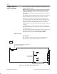
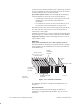
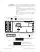
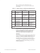
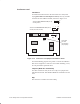
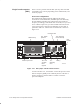
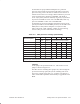
Table Of Contents
- Title page
- Contents
- About this manual
- Safety information
- Ch 1 - Introduction
- Ch 2 - Adding cards to the Controller
- Unpacking the System Controller
- Unpacking the picocells
- System Controller card configuration
- Adding cards to the System Controller (first steps)
- Jumper and DIP switch settings
- Attaching bus cables
- Adding cards to the System Controller (final steps)
- Configuring Controller cards
- Verifying the card configuration
- Ch 3 - Installing the Controller
- Ch 4 - Verifying the Controller configuration
- Ch 5 - Configuring the router
- Ch 6 - Testing picocells
- Ch 7 - Installing picocells
- Ch 8 - Connecting to external equipment
- Ch 9 - System testing
- Ch 10 - Installation inspection
- Ch 11 - Provisioning
- Ch 12 - Remote Client
- Ch 13 - Troubleshooting
- Ch 14 - Maintaining Quad T1 cards
- App A - Specifications
- App B - Standards compliance information
- App C - Part numbers
- App D - Updates and backups
- Index

1026209–0001 Revision B
Adding cards to the System Controller 2–15
This section applies to both the TX2000 IP card (factory installed
in slot 16) and the TX2000 SS7 (optional, slot 15). Most settings
are the same for both cards; those that are different are clearly
pointed out.
The key settings to check on the TX2000 cards are the IRQ and
I/O address. All jumpers other than JP7 (IRQ selection) should be
left in their factory default positions.
Jumpers
Make sure the IRQ selection jumper is in position 7, as shown in
Figure 2-11. (The factory default is IRQ 10. “NO” disables the
ISA bus.) Use IRQ 7 only.
Figure 2-11 Jumpers and address switch on TX2000 IP and TX2000 SS7 cards
JP1
JP9
JP2
JP16
JP14
S1
IRQ
ON
13
14
15
16
17
18
Address for 0xD4000
(ON, OFF, ON, OFF, ON, OFF, as shown)
TX2000 IP:
ON
13
14
15
16
17
18
Address for TX2000 SS7: 0xD6000
(OFF, OFF, ON, OFF, ON, OFF, as shown)
TX2000 IP:
TX2000 SS7:
Connect JP14 pins and connect JP16 pins, as shown.
connect these jumpers.
DO NOT
JP1: Connect two
jumpers vertically.
>8
32
JP2: Connect
top pins.
NO
15
14
12
11
10
9
7
5
4
3
Set to IRQ 7.
JP9: Connect
upper pins.
T0001015
TX2000 IP and
TX2000 SS7 cards