
Installation Instructions
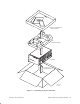
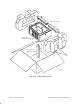
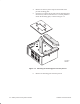
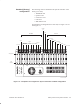
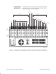
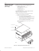
Table Of Contents
- Title page
- Contents
- About this manual
- Safety information
- Ch 1 - Introduction
- Ch 2 - Adding cards to the Controller
- Unpacking the System Controller
- Unpacking the picocells
- System Controller card configuration
- Adding cards to the System Controller (first steps)
- Jumper and DIP switch settings
- Attaching bus cables
- Adding cards to the System Controller (final steps)
- Configuring Controller cards
- Verifying the card configuration
- Ch 3 - Installing the Controller
- Ch 4 - Verifying the Controller configuration
- Ch 5 - Configuring the router
- Ch 6 - Testing picocells
- Ch 7 - Installing picocells
- Ch 8 - Connecting to external equipment
- Ch 9 - System testing
- Ch 10 - Installation inspection
- Ch 11 - Provisioning
- Ch 12 - Remote Client
- Ch 13 - Troubleshooting
- Ch 14 - Maintaining Quad T1 cards
- App A - Specifications
- App B - Standards compliance information
- App C - Part numbers
- App D - Updates and backups
- Index

1026209–0001 Revision B
Adding cards to the System Controller 2–9
The following cards are installed in the System Controller at the
factory (one each):
• TX2000 IP card
• Quad T1 card
• Conference card
• LAN card
• 56K modem card
For backplane slot assignments for each card, see Figure 2-6. See
also Figure 2-7.
PCI
9
PCI
8
PCI
7
PCI
6
PCI
5
PCI
4
PCI
3
PCI
2
PCI
1
ISA
1
ISA
2
ISA
3
ISA
4
ISA
5
ISA
6
ISA
7
ISA
8
56K modem
Spare
Spare
Spare
TX2000 IP
Spare
Spare
Conf card 1
SBC
LAN 1
1
Spares
23456
Quad T1
Slot type ID
G-17192 F 02/24/00
PCI slots
ISA slots
Parallel
port
7
(Not used)
Spare
Slot
number
123 45 678910111213
14 15 16 17 18 19 20
Figure 2-6 Backplane slot assignments: System Controller standard configuration
Standard (factory)
configuration