
Installation Instructions
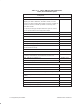
Table Of Contents
- Title page
- Contents
- About this manual
- Safety information
- Ch 1 - Introduction
- Ch 2 - Adding cards to the Controller
- Unpacking the System Controller
- Unpacking the picocells
- System Controller card configuration
- Adding cards to the System Controller (first steps)
- Jumper and DIP switch settings
- Attaching bus cables
- Adding cards to the System Controller (final steps)
- Configuring Controller cards
- Verifying the card configuration
- Ch 3 - Installing the Controller
- Ch 4 - Verifying the Controller configuration
- Ch 5 - Configuring the router
- Ch 6 - Testing picocells
- Ch 7 - Installing picocells
- Ch 8 - Connecting to external equipment
- Ch 9 - System testing
- Ch 10 - Installation inspection
- Ch 11 - Provisioning
- Ch 12 - Remote Client
- Ch 13 - Troubleshooting
- Ch 14 - Maintaining Quad T1 cards
- App A - Specifications
- App B - Standards compliance information
- App C - Part numbers
- App D - Updates and backups
- Index

1026209–0001 Revision B Index-1
Index
A
AIReach Office application
banner window, 2–28
launching, 2–28, 4–2
Alarm paging, 8–11
Alarms, picocells, 13–8
table, 13–9
Antenna, picocell, A–6
Applications (list of AIReach OS applications),
2–27
AROS Configuration icon, 2–28
AROSC Configuration window, 2–29, 4–3
AROSC Name, 4–3
ArosPageInfo.dat file, 8–12
B
Backing up databases, D–2
Backplane slots. See Controller, slots, and
Picocell, slots
Band scan. See Frequency band scan
Banner window for AIReach Office application,
2–28
Block diagram, 1–2
BTCs. See Transceivers (picocells)
BTS Configuration window, 4–14
Bus adapter card, 2–23, 14–3
C
Cables
H.100 bus, 2–23, 14–2
MVIP bus, 2–23, 14–2
picocells, 7–7
router connections, 5–2
test cable (picocell to Quad T1 card), 6–2
Cabling, 3–7
Controller, 3–5
Controller to PBX, 8–2
external modem, 8–11
picocell, 7–9
T1, picocells, 7–11, 7–16
wiring flip, 7–16
Cards (Controller)
adding, 2–11
configuring, 2–25
DIP switch settings, 2–13
fully loaded configuration, 2–10
jumper settings, 2–13
slot assignments, 2–9
standard configuration, 2–1, 2–9
types, 1–6
verifying configuration, 2–27, 4–4
Cell Configuration window, 4–12
Conference cards
adding to Controller configuration, 2–31
DIP switch settings, 2–18
jumper settings, 2–18
MVIP bus, 2–23
Configuration options, 1–12
Configuration Report, 2–1, 2–25, 4–2,
6–1, 7–7
correcting to reflect installation, 9–2
Configuring
Controller cards, 2–25
HLR, 4–21
Quad T1 cards, 14–6
router, 5–2
Connectors
picocells
illustrated, 7–10
T1 cable, 7–8
picocells (illustrated), 6–3
Quad T1 card, 6–4
Controller
cabling, 3–5
card types, 1–6
cards
adding, 2–11
configuring, 2–25
DIP switch settings, 2–13
fully loaded configuration, 2–10
jumper settings, 2–13
slot assignments, 2–9
standard configuration, 2–1, 2–9
verifying configuration, 2–27, 4–4
chassis cover, 2–11, 2–24