
Installation Instructions
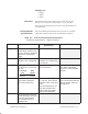
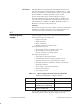
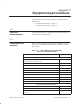
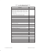
Table Of Contents
- Title page
- Contents
- About this manual
- Safety information
- Ch 1 - Introduction
- Ch 2 - Adding cards to the Controller
- Unpacking the System Controller
- Unpacking the picocells
- System Controller card configuration
- Adding cards to the System Controller (first steps)
- Jumper and DIP switch settings
- Attaching bus cables
- Adding cards to the System Controller (final steps)
- Configuring Controller cards
- Verifying the card configuration
- Ch 3 - Installing the Controller
- Ch 4 - Verifying the Controller configuration
- Ch 5 - Configuring the router
- Ch 6 - Testing picocells
- Ch 7 - Installing picocells
- Ch 8 - Connecting to external equipment
- Ch 9 - System testing
- Ch 10 - Installation inspection
- Ch 11 - Provisioning
- Ch 12 - Remote Client
- Ch 13 - Troubleshooting
- Ch 14 - Maintaining Quad T1 cards
- App A - Specifications
- App B - Standards compliance information
- App C - Part numbers
- App D - Updates and backups
- Index

1026209–0001 Revision B
Equipment specifications A–5
Shipping size
• Height:
• Width:
• Depth:
The picocell is line powered using the T1 cable. The picocell
operates over an input dc voltage range of –24 to –54 volts.
For dc power, the maximum power draw of the picocell does not
exceed 50 watts.
The environmental specifications for the picocell are consistent
with indoor commercial electronic communication products.
Table A-2 Picocell environmental specifications
Preliminary specifications – subject to change
Operational Non–operational
(unpackaged)
Non–operational (packaged)
Temperature
0_C to +50_C
Temperature gradient of up
to 8.3_C per hour within the
operational temperature
range
–40_C to +65_C
Humidity
10% to 95% relative
humidity, non–condensing
10% to 95% relative
humidity non–condensing,
not powered
Vibration
0.5–g rms random, 5 to 500
Hz, three axes, 10 minutes
per axis
Frequency PSD
(Hz) (g
2
/Hz)
5–350 0.00060
350–500 0.00029
1.5 g peak acceleration
from 10 to 50 Hz
3g peak acceleration from
50 to 500 Hz (Example
transport in turbo propeller
aircraft).
Shock
10g at 11 ms, 1/2 sine,
three shocks applied to
each of the three axes.
Non–operational: 60g at 11
ms, 1/2 sine, three shocks
applied to each of the three
axes.
Non–operational drop: 12
inch drop complies with
Bellcore GR–63–CORE,
1995 test configuration
Non–operational: 36 inch
drop complies with Bellcore
GR–63–CORE, 1995 test
configuration
Altitude
200 feet below sea level to
10,000 feet above sea level
when the specifications
meet temperature and
humidity limits
Electrical
Environmental
specifications