
Installation Instructions
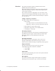
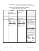
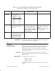
Table Of Contents
- Title page
- Contents
- About this manual
- Safety information
- Ch 1 - Introduction
- Ch 2 - Adding cards to the Controller
- Unpacking the System Controller
- Unpacking the picocells
- System Controller card configuration
- Adding cards to the System Controller (first steps)
- Jumper and DIP switch settings
- Attaching bus cables
- Adding cards to the System Controller (final steps)
- Configuring Controller cards
- Verifying the card configuration
- Ch 3 - Installing the Controller
- Ch 4 - Verifying the Controller configuration
- Ch 5 - Configuring the router
- Ch 6 - Testing picocells
- Ch 7 - Installing picocells
- Ch 8 - Connecting to external equipment
- Ch 9 - System testing
- Ch 10 - Installation inspection
- Ch 11 - Provisioning
- Ch 12 - Remote Client
- Ch 13 - Troubleshooting
- Ch 14 - Maintaining Quad T1 cards
- App A - Specifications
- App B - Standards compliance information
- App C - Part numbers
- App D - Updates and backups
- Index
1026209–0001 Revision B A–2 Equipment specifications
The System Controller requires a standard electrical outlet
(NEMA 15P) located within 6 feet.
The power supply provides power only to the System Controller.
When battery backup is required, a UPS (uninterruptable power
source) unit is necessary.
The ac input connects to a single phase, two–wire service. This
interface occurs through a standard IEC 320 style connector. The
power cord is of a double reinforced insulation design as required
by safety agencies.
Voltage, frequency, and phase
The input voltage, frequency, and phase are:
• Input voltage:
- Low range: 95 Vac to 132 Vac nominal 110–125 Vac
- High range: 190 Vac to 263 Vac nominal 230–240 Vac
• Input frequency: range 47 Hz to 63 Hz
• Input phase: single, three–wire earthed interface
• Consumption: < 700 watts
AC input protection
The System Controller has an internal fuse. Limited protection is
provided from power surges or other transients on the dc input.
This meets with the levels provided by IFC–801–4 and
IEC–801–2.
AC input connection
The ac input connects to a single phase, three–wire service
through a standard IEC 320 connector. The power cord is a
double/reinforced insulation design as required by safety agencies.
Surge protection
The surge requirements on the ac power line meet the
requirements of the IEC 61–000–4–5 standards:
• ±1 kV (DM)
• ±2 kV (CM)
Power draw
For dc power, the maximum power draw of the System Controller
does not exceed 400 watts.
Bus support
The System Controller’s single–board computer is capable of
sinking up to 64 mA and source up to 32 mA for the ISA bus.
Electrical