
Installation Instructions
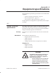
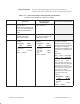
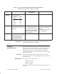
Table Of Contents
- Title page
- Contents
- About this manual
- Safety information
- Ch 1 - Introduction
- Ch 2 - Adding cards to the Controller
- Unpacking the System Controller
- Unpacking the picocells
- System Controller card configuration
- Adding cards to the System Controller (first steps)
- Jumper and DIP switch settings
- Attaching bus cables
- Adding cards to the System Controller (final steps)
- Configuring Controller cards
- Verifying the card configuration
- Ch 3 - Installing the Controller
- Ch 4 - Verifying the Controller configuration
- Ch 5 - Configuring the router
- Ch 6 - Testing picocells
- Ch 7 - Installing picocells
- Ch 8 - Connecting to external equipment
- Ch 9 - System testing
- Ch 10 - Installation inspection
- Ch 11 - Provisioning
- Ch 12 - Remote Client
- Ch 13 - Troubleshooting
- Ch 14 - Maintaining Quad T1 cards
- App A - Specifications
- App B - Standards compliance information
- App C - Part numbers
- App D - Updates and backups
- Index
1026209–0001 Revision B 14–10 Maintaining Quad T1 card
7. The AROSHWCfg window lists the Quad T1 boards.
8. In the AROSHWCfg window, select the card with the same
PC slot number as the card previously deleted; then click
Delete to remove the card.
9. Click OK to exit the AROSHWCfg utility.
10. Shut down the Controller: Click Start → Shutdown, select
Shut down the computer?, and click Yes .
11. After you see the message indicating that it’s OK to turn off
power to the computer, turn off the Controller power
switch.
To remove the card from the chassis:
1. Remove the Controller cover (as explained on page 2–11).
2. Remove any PBX or BTS connections to the back of the
Quad T1 to be removed.
3. Disconnect the H.100 ribbon cable (shown in Figure 14-1)
from the card to be removed.
4. If the card to be removed is the first one in a chain of Quad
T1 cards (typically in slot 9), remove the MVIP cable also.
(This cable is shown in Figure 14-1.)
5. Unscrew the hold–down screw for the card to be removed.
6. Remove the card by carefully lifting it up.
7. Install a blank panel in the slot where the card was removed
and attach it with the hold–down screw from the card that
was removed.
8. Reconnect the H.100 cable (as necessary) so it connects to
all Quad T.1 cards (as shown in Figure 14-1).
9. If the card removed had the MVIP–to–H.100 bus adapter
card attached to it (Figure 14-1 on page 14–2), remove the
bus adapter card and install it on the card that is now at the
end of the Quad T1 card chain. See Figure 14-2 on
page 14–3.
10. If the card removed was at either end of the Quad T1 card
chain, set the S1 DIP switches on the card now at the end of
the chain to ON to enable termination.
11. Replace the Controller cover.
Be careful not to damage the copper finger stock under the
front edge of the cover.
12. Turn the power switch on and wait for the Controller to
boot up.
13. After all processes on the Controller have started, verify
that the new card is operational by checking the state of any
BTSs connected to the card and any PBX connections to the
card.
For details, see steps 19 and 20 on page 14–4.
Physically removing
the card