
Installation Instructions
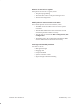
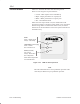
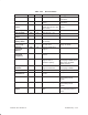
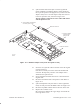
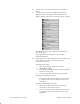
Table Of Contents
- Title page
- Contents
- About this manual
- Safety information
- Ch 1 - Introduction
- Ch 2 - Adding cards to the Controller
- Unpacking the System Controller
- Unpacking the picocells
- System Controller card configuration
- Adding cards to the System Controller (first steps)
- Jumper and DIP switch settings
- Attaching bus cables
- Adding cards to the System Controller (final steps)
- Configuring Controller cards
- Verifying the card configuration
- Ch 3 - Installing the Controller
- Ch 4 - Verifying the Controller configuration
- Ch 5 - Configuring the router
- Ch 6 - Testing picocells
- Ch 7 - Installing picocells
- Ch 8 - Connecting to external equipment
- Ch 9 - System testing
- Ch 10 - Installation inspection
- Ch 11 - Provisioning
- Ch 12 - Remote Client
- Ch 13 - Troubleshooting
- Ch 14 - Maintaining Quad T1 cards
- App A - Specifications
- App B - Standards compliance information
- App C - Part numbers
- App D - Updates and backups
- Index

1026209–0001 Revision B 13–8 Troubleshooting
Table 13-1 describes the alarm codes from the picocell.
There are four categories of picocell alarms:
• Critical – BTS requires service immediately
• Major – Major performance or capacity loss
• Minor – Minor performance or capacity loss
• Info – Informational alarm
When critical or major alarms occur, the Alarm LED on the
picocell front panel is red. When a minor alarm occurs, the Alarm
LED is orange. When an information alarm occurs, the Alarm
LED is not lit: the information is sent to the System Controller for
information only.
Figure 13-1 LEDs on front of picocell
T0001003
Power
Green - Voltage normal
Orange - Low voltage
Alarm (Controller)
Off - Normal
Orange - Minor alarm
Red - Major alarm
Temperature (power supply)
Green - Normal
Red - Exceeds 75° C
Power
Te mp
Alarm
Alarm LED is orange while
the Controller boots.
Note
The LED information above is for production picocells. LED
codes may be different for pre–production picocells.
13.4
Picocell alarms