
Installation Instructions
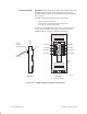
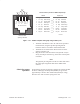
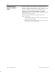
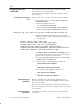
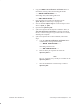
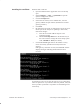
Table Of Contents
- Title page
- Contents
- About this manual
- Safety information
- Ch 1 - Introduction
- Ch 2 - Adding cards to the Controller
- Unpacking the System Controller
- Unpacking the picocells
- System Controller card configuration
- Adding cards to the System Controller (first steps)
- Jumper and DIP switch settings
- Attaching bus cables
- Adding cards to the System Controller (final steps)
- Configuring Controller cards
- Verifying the card configuration
- Ch 3 - Installing the Controller
- Ch 4 - Verifying the Controller configuration
- Ch 5 - Configuring the router
- Ch 6 - Testing picocells
- Ch 7 - Installing picocells
- Ch 8 - Connecting to external equipment
- Ch 9 - System testing
- Ch 10 - Installation inspection
- Ch 11 - Provisioning
- Ch 12 - Remote Client
- Ch 13 - Troubleshooting
- Ch 14 - Maintaining Quad T1 cards
- App A - Specifications
- App B - Standards compliance information
- App C - Part numbers
- App D - Updates and backups
- Index

1026209–0001 Revision B
Installing picocell 7–17
Figure 7-12 T568B–compliant wiring flip using modular jack
RJ-45 connector pinout for T568B-compliant flip
T568B
Flipped end
Pin Signal Color code Pin Signal Color code
1 TX Ring White-orange 5 RX Ring White-blue
2 TX Tip Orange-white 4 RX Tip Blue-white
3 Pos DC White-green 3 Pos DC White-green
4 RX Tip Blue-white 1 TX Ring White-orange
5 RX Ring White-blue 2 TX Tip Orange-white
6 Neg DC Green-white 6 Neg DC Green-white
7 Pos DC White-brown 7 Pos DC White-brown
8 Neg DC Brown-white 8 Neg DC Brown-white
View from front
opening, tab down
12345678
W-O
O
W-G
BL
W-BL
G
W-BR
BR
Pin and color code
Pair 2 Pair 1 Pair 4
Pair 3
T0001020
1. Terminate and label the CAT 5 T1 cable on the specified
terminal block, using the specified pin assignments.
Label the cables in accordance with TIA/EIA–606.
2. Terminate the T1 cable with an RJ–45 connector at the
System Controller end.
3. Plug the RJ–45 connector into the first Quad T1 card (in
slot 9), second port from the top, at the back of the System
Controller.
Note
The physical port assignment for the T1 cable must match
the virtual port assignment made in the AIReach OS
software.
Verify that the picocell successfully completes its self test and that
the Power LED (top) and Temp LED (middle) are green after
approximately 2 minutes. The Alarm LED (bottom) is orange,
then turns off—this is normal cycling of the unit.
Check for proper
operation