
Installation Instructions
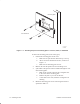
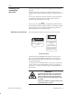
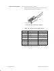
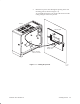
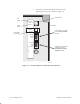
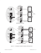
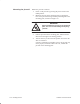
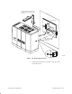
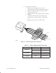
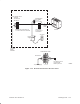
Table Of Contents
- Title page
- Contents
- About this manual
- Safety information
- Ch 1 - Introduction
- Ch 2 - Adding cards to the Controller
- Unpacking the System Controller
- Unpacking the picocells
- System Controller card configuration
- Adding cards to the System Controller (first steps)
- Jumper and DIP switch settings
- Attaching bus cables
- Adding cards to the System Controller (final steps)
- Configuring Controller cards
- Verifying the card configuration
- Ch 3 - Installing the Controller
- Ch 4 - Verifying the Controller configuration
- Ch 5 - Configuring the router
- Ch 6 - Testing picocells
- Ch 7 - Installing picocells
- Ch 8 - Connecting to external equipment
- Ch 9 - System testing
- Ch 10 - Installation inspection
- Ch 11 - Provisioning
- Ch 12 - Remote Client
- Ch 13 - Troubleshooting
- Ch 14 - Maintaining Quad T1 cards
- App A - Specifications
- App B - Standards compliance information
- App C - Part numbers
- App D - Updates and backups
- Index

1026209–0001 Revision B
Installing picocell 7–7
This procedure applies to both the scanning picocell and traffic
picocells.
Install the scanning picocell in its permanent location prior to
completing the 24–hour (minimum) frequency band scan (section
7.4).
To save time, initiate the 24–hour frequency band scan (Section
7.4) and then install the traffic picocells at their permanent
locations while the band scan is running.
Note
The site–specific AIReach Office Configuration Report contains
the information needed to install the picocells, including locations
where picocells are to be installed, cable labeling, punchdown
block assignments, and required fasteners.
The following labels appear on the picocell connector panel:
Labels on picocell
SWITCH POWER OFF
BEFORE CONNECTING
OR DISCONNECTING
CABLES
WARNING
CAUTION
TO REDUCE THE RISK OF
FIRE, USE ONLY No. 24
AWG OR LARGER LISTED
TELECOMMUNICATIONS
LINE CORD.
FOR CONTINUED
PROTECTION AGAINST
RISK OF FIRE, REPLACE
ONLY WITH SAME TYPE
AND RATING OF FUSE.
T0001022
As indicated by the WARNING label, make sure the picocell
power switch is OFF (middle position) before connecting or
disconnecting cables. This is to protect the picocell connectors
from possible damage.
As indicated by the CAUTION label, use only No. 24 AWG line
cord to connect to the VOICE/DATA ports. If you replace the
picocell fuse, use only a fuse of the type and rating identified on
the fuse label.
WARNING
To reduce the risk of fire, use only No. 24
AWG or larger line cord to connect to the
picocell, and replace the fuse only with a
fuse of the type and rating identified on the
fuse label.
Failure to heed these warnings could result
in personal injury or death.
7.3
Installing and
connecting
picocells
Warnings and cautions