
Installation Instructions
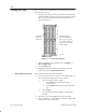
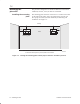
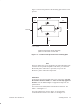
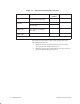
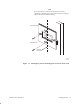
Table Of Contents
- Title page
- Contents
- About this manual
- Safety information
- Ch 1 - Introduction
- Ch 2 - Adding cards to the Controller
- Unpacking the System Controller
- Unpacking the picocells
- System Controller card configuration
- Adding cards to the System Controller (first steps)
- Jumper and DIP switch settings
- Attaching bus cables
- Adding cards to the System Controller (final steps)
- Configuring Controller cards
- Verifying the card configuration
- Ch 3 - Installing the Controller
- Ch 4 - Verifying the Controller configuration
- Ch 5 - Configuring the router
- Ch 6 - Testing picocells
- Ch 7 - Installing picocells
- Ch 8 - Connecting to external equipment
- Ch 9 - System testing
- Ch 10 - Installation inspection
- Ch 11 - Provisioning
- Ch 12 - Remote Client
- Ch 13 - Troubleshooting
- Ch 14 - Maintaining Quad T1 cards
- App A - Specifications
- App B - Standards compliance information
- App C - Part numbers
- App D - Updates and backups
- Index

1026209–0001 Revision B 7–4 Installing picocell
Table 7-1 Approved mounting plate fasteners
Surface Fastener Fastener part
number
Hole locations
1
Drywall (hollow) E–Z Anchor self–drilling
drywall anchor and screw
9010193–0001 1, 2, 3, 4
Concrete block or
t
Lead anchor for 10–24 screw 9004929–0001
1, 2, 3, 4
concrete
Phillips head machine screw,
10–24 x 3/4”
9003333–0074
Metal wall or
metal studs
Sheet metal screw,
self–drilling, self–tapping,
10 x 3/4”
1028868–0018 1, 3
Wood wall or
wood studs
Wood screw, 10 x 1–1/4” 1028228–0021 1, 3
1
As shown in figures 7-3 and 7-4.
If the picocell is located near a door, make sure the door opens
without hitting the picocell:
1. Mount the picocell so the bottom of the picocell is above
the top of the door and door hardware, or
2. Mount the picocell far enough from the door so the door can
open fully without hitting the picocell.