
Installation Instructions
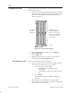
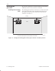
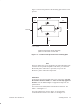
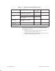
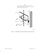
Table Of Contents
- Title page
- Contents
- About this manual
- Safety information
- Ch 1 - Introduction
- Ch 2 - Adding cards to the Controller
- Unpacking the System Controller
- Unpacking the picocells
- System Controller card configuration
- Adding cards to the System Controller (first steps)
- Jumper and DIP switch settings
- Attaching bus cables
- Adding cards to the System Controller (final steps)
- Configuring Controller cards
- Verifying the card configuration
- Ch 3 - Installing the Controller
- Ch 4 - Verifying the Controller configuration
- Ch 5 - Configuring the router
- Ch 6 - Testing picocells
- Ch 7 - Installing picocells
- Ch 8 - Connecting to external equipment
- Ch 9 - System testing
- Ch 10 - Installation inspection
- Ch 11 - Provisioning
- Ch 12 - Remote Client
- Ch 13 - Troubleshooting
- Ch 14 - Maintaining Quad T1 cards
- App A - Specifications
- App B - Standards compliance information
- App C - Part numbers
- App D - Updates and backups
- Index

1026209–0001 Revision B
Installing picocell 7–3
Figure 7-2 shows the position of the mounting plate relative to the
picocell.
1.5” 2.0”
1.375”
2.75”
G-17371 F 08/24/99
1
2
3
4
Figure 7-2 Position of the picocell on the mounting plate
Notice that clearance for the mounting
plate is not the same on each side.
Picocell
Note
This note applies only to pre–production picocells: Mounting plate
revisions are not upward compatible. This means you cannot use
Revision B plates on Revision C picocells, but you can use
Revision C plates on Revision B picocells.
Fasteners
To mount the picocell mounting plate to the wall surface, use only
the fasteners shown in Table 7-1 —these are the only approved
fasteners. See the AIReach Office Configuration Report for site
specifications.
For wood or metal studs, HNS recommends two fasteners. See
Table 7-1 and Figure 7-3.
For walls composed of concrete, block, or drywall, HNS
recommends four fasteners. See Table 7-1 and Figure 7-4.