User Guide Thuraya IP+ Satellite Modem Revision A 3500799-0001 PROPRIETARY NOTICE All rights reserved. This publication and its contents are proprietary to Hughes Network Systems, LLC. No part of this publication may be reproduced in any form or by any means without the written permission of Hughes Network Systems, LLC, 11717 Exploration Lane, Germantown, Maryland 20876. HUGHES, HughesNet, IPoS, SPACEWAY, AIReach, Broadband Unbound, and Connect to the future are trademarks of Hughes Network Systems, LLC.
Safety Information For your safety and protection, read this entire user guide before you attempt to use Thuraya IP+ Satellite Modem. In particular, read this safety section carefully. Keep this safety information where you can refer to if necessary. Warning Symbols Used in this Guide This section introduces the various types of warnings used in this document to alert you to possible safety hazards. WARNING Potential radio frequency (RF) hazard.
WARNINGS FOR THURAYA IP+ Do not stand in front of the Antenna This device emits radio frequency energy when in the transmit mode. To avoid injury, do not place head or other body parts in front of the satellite antenna when system is operational. Maintain a distance of one meter away from the front of antenna. Properly ground the Antenna Failure to properly ground the optional external antenna may result in severe personal injury or death.
chemicals. Qualified service Do not attempt to disassemble your Thuraya IP+. Thuraya IP+ does not contain consumer-serviceable components. Only qualified service personnel may install or repair equipment. Batteries and accessories Use approved batteries (Hughes P/N 3500496-0001) and accessories only. Use of non-approved accessories may result in loss of performance, damage to Thuraya IP+, fire, electric shock or injury. AC Mains power adapter (Hughes P/N 3500411-0002) is for indoor use only.
your Thuraya IP+ immediately! Hearing aids Most new models of hearing aids are immune to radio frequency interference from Satellite Modems that are more than 2 metres away. Many types of older hearing aids may be susceptible to interference, making it very difficult to use them near a Satellite Modem. Should interference be experienced, maintain additional separation between you and Thuraya IP+.
Contents SAFETY INFORMATION ............................................................................................................. I WARNING SYMBOLS USED IN THIS GUIDE .................................................................................... I WARNINGS FOR THURAYA IP+ ..................................................................................................... II CONTENTS ...............................................................................................................
UPGRADING THURAYA IP+ ......................................................................................................... 27 UPGRADING SOFTWARE ......................................................................................................... 27 TROUBLESHOOTING............................................................................................................... 28 GENERAL TROUBLESHOOTING ..................................................................................................
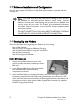
Introduction Your Thuraya IP+ is a Satellite Modem that provides portable, high-speed data communications via satellite. Using “Always On” technology, you can remain connected to the Internet while only sending or receiving the data that you need at speeds of up to 444kbits/s, just as if you were sitting at your office desk. Thuraya IP+ works with your computer using an Ethernet or Wi-Fi connection much like commercially available wireless routers.
Software Installation and Configuration Your PC must support an Ethernet or Wireless LAN interface to operate with the Thuraya IP+. Note: You must verify that the proxy server settings in your browser are disabled. For Microsoft Internet Explorer, select Tools / Internet Options / Connections / LAN Settings and uncheck the box labelled ‘Use a proxy server for your LAN’. For Firefox, go to Advanced Preferences and select ‘Direct connection to the Internet’. When complete please close your browser.
STEP 2: POWER CONNECTION AND BATTERY CHARGING 1. The Thuraya IP+ will charge the battery automatically when power is connected. 2. Plug in Power cable and charge the battery for at least three hours. STEP 3: OBTAIN INITIAL GPS USING THE THURAYA IP+ 1. Put the Thuraya IP+ outside on a flat surface with a clear view of the sky away from building, trees and other obstructions. 2. Power up Satellite Modem by pressing the Power button. 3.
URL address field Note: You may want to store this as a browser bookmark. 2. If you have PIN security enabled on your SIM, you will be prompted to enter your PIN before proceeding. Note: You must have a valid GPS location for the compass direction and Antenna Angle to be displayed. If the GPS is not valid, go back to step 3 to obtain a GPS fix. Compass Direction Antenna Angle 3.
satellite as determined in step 3. 5. You can optimise the receive signal strength by observing the signal strength display on the Thuraya IP+ while slowly rotating the Thuraya IP+ a few degrees clockwise and counter clockwise. Find the direction that maximizes the signal strength. Likewise, slowly raise and lower the antenna a few degrees and find the elevation that maximizes the signal strength. This step fine tunes the pointing of the antenna in the direction of the Thuraya IP+ satellite.
Quick Reference This section serves as a reference guide, identifying the key operational aspects of using the Thuraya IP+ system and the Controls and Indicators on Thuraya IP+ and their functions. Global Positioning System Operation The Thuraya IP+ contains an integrated Global Positioning System (GPS) receiver that is used to provide location information.
Integrated Man Machine Interface (iMMI) The Thuraya IP+ has an Integrated Man Machine Interface (iMMI) which allows you to control the operational features of the terminal without the need of a PC or a browser. The iMMI includes buttons labelled with defining icons, an LCD, and an audible pointing aid integrated into the Thuraya IP+ itself. The figure below shows the layout of the Thuraya IP+ iMMI.
STATUS/MENU DISPLAY The upper level of the LCD displays status messages and menu items. Status messages are summarized in the table below.
Press the Modify button. You are then brought to the first value in the series of QoS settings.
When you select a new QoS, the old PDP context is deactivated and a new PDP context is activated with the new rate selection. If the rate selection did not change as a result of the selection, then no PDP context change occurs. RECEIVE SIGNAL STRENGTH DISPLAY The lower row of the LCD is dedicated to RSSI (signal strength) information. This is used to monitor incoming signal strength from the Thuraya satellite and permit pointing or re-pointing to occur at any time during operation.
The icon is on steady when the stored GPS information is within the GPS validity period. Satellite Icons: The satellite icons, located next to the GPS icon, indicate the status of the GPS receiver in the Thuraya IP+ and the number of visible satellites. The icons are off when the GPS receiver is off. The icons are active when the GPS receiver is on, either flashing or steady state. The number of icons in steady state indicates the number of GPS satellites in view.
Each of the main web pages contains important status information in the upper left hand corner. The bar graph next to the icon represents receive signal strength. The bar graph next to the icon provides an indication of the battery’s level and charging state. The icon area below these indicators mirrors the icons described in the iMMI section above. During a streaming session this area also maintains a timer to record how long the session has lasted.
Connect/Disconnect: This button toggles the network connection state on or off. When Disconnected no data can be sent or received. Change Data Rate: This button allows you to change the connection parameters for the current session. Quick Connect: These buttons access pre-stored connection profiles. GPS: The display includes the GPS receiver state (On/Off), GPS satellites visible, GPS validity, compass direction and antenna angle.
Extract Terminal Summary Log: Fetched diagnostic data from the terminal which can be saved on the connected computer. Current Settings: provides the current communications parameters.
CONNECTION MANAGEMENT SCREEN Accessible from the Main Menu, the Connection Management Screen allows you to select from nine Quality of Service (QoS) quick connect buttons. Each button can be customized using the Details link on the Connection Management Screen. The customization parameters for each button are as follows: Transmit Rate and Receive Connection Rate: Allows you to select the transmit and receive rates from the list of bandwidth values.
STATUS SCREEN The Status Screen, displayed in a separate window, provides you with a constantly updated flow of dynamic information and a concise summary of the Thuraya IP+ status. When the Status Screen is open, its information is updated every minute. Note that while on battery power, your operating time will be reduced. Network Status: Provides the status of the network connection. Signal Quality: This bar graph displays satellite signal quality.
SETTINGS SCREENS From the Main menu you can select Settings to navigate among all the various Settings functions from the menu on the left side of the screen: Network Settings Security Management Settings Login Settings WLAN Settings Advanced Settings NETWORK SETTINGS SCREEN After executing the necessary First Time Set-up steps to configure Thuraya IP+, you may want to select the Network Settings Screen to check your network configuration.
the wMMI and the base address for the Ethernet DHCP server. This subnet must remain unique from the WLAN subnet address being used. DHCP Server: The DHCP server for Ethernet can be enabled or disabled as needed. If disabled, a local static IP addressing scheme must be used by connected Ethernet devices. This setting has no impact on the WLAN operation which uses a dedicated DHCP server. Netmode: This command allows for NAT or Relay Mode to be selected.
SECURITY MANAGEMENT SCREEN The Security Management Screen allows you to impose a tighter level of security on your Thuraya IP+. SIM PIN Disable/Enable: If Enabled, a prompt requests you to enter the SIM PIN each time you power up the modem. This helps prevent unauthorised use of your SIM. Disable this feature to skip the PIN entry process. To change the setting, click the desired one, enter the current SIM PIN (required), and click the Save button.
LOGIN SETTINGS SCREEN Utilize the Login Screen only if you have been given the necessary information from your Service Provider. Service Provider Security: If this is enabled, you can enter a User Name and Password for authentication between Thuraya IP+ and your Service Provider. Your Service Provider will let you know if this step is required and give you the necessary information. User Name, Password, Confirm Password: You must enter the password twice to ensure accuracy.
WLAN CONFIGURATION SCREEN The WLAN Configuration Screen allows you to configure the integrated WLAN Access Point (AP) which can support up to eight simultaneous clients using 802.11b/g/n. The WLAN AP operates on its own subnet and utilizes its own DHCP server. The wMMI remains at 192.168.128.100 (default) whether accessed via WLAN or Ethernet. WLAN Power: Select ON or OFF to turn the feature on or off. WLAN Power Off timeout: If disabled, there is no timeout.
WLAN SECURITY SCREEN The WLAN Security Screen allows you to configure WLAN security parameters, including enabling/disabling Wired Equivalent Privacy (WEP), hiding the SSID and setting Media Access Control (MAC) filters. Access this screen by clicking the WLAN Security Settings link towards the bottom of the WLAN Configuration Screen. WLAN SSID Broadcast: Enable or Disable SSID broadcast. Security: Disable or chose an available security method: Wired Equivalent Privacy (WEP64 or WEP128), WPA or WPA2.
ADVANCED SETTINGS SCREEN The Advanced Settings Screen allows you to modify several key operating parameters in the unit. Satellite Search Method: Normal is the default method to use unless your Service Provider specifies the Full Method. The Full method takes longer and utilizes more resources since it will search all possible frequencies for Thuraya IP+ service. This full search can take up to 20 minutes. Auto Power ON: When enabled, the terminal will automatically power up when external DC is applied.
data). You can cancel the alert by pressing an iMMI button. When the visual streaming alert is enabled, the terminal will flash the LCD backlight every 10 seconds during any streaming QoS session unless the backlight is set to off. The audio and visual streaming alert indicators can be enabled or disabled separately or used in conjunction with each other using the Streaming Alert control.
Pointing Screen The Antenna Pointing Screen step can be enabled using the Antenna Pointing option on advanced settings screen described above. When this option is enabled, the Thuraya IP+ will stop in a pointing mode prior to accessing the network after powering up. This can be useful when optimal pointing is important, such as with fixed installations using an external antenna. The pointing screen has a signal strength bar graph and numeric value to assist in accurate antenna pointing.
REMOTE ACCESS SCREEN The Remote Access Screen enables wMMI access from the satellite side of the terminal. To use the feature, select the Enabled option, type in a password and select Save. Obtain the Network IP Address from the Properties Screen and use that in the browser on the remote PC as follows: http://85.115.79.53:45380 (85.115.79.53 is an example; your terminal address will be different and can change with each PDP session). In general the IP address to use is http://aaa.bbb.ccc.
UPGRADING THURAYA IP+ Should a Thuraya IP+ Modem software upgrade become available, you can complete the upgrade process yourself. The software can be downloaded directly from the Internet using any available access method, including Thuraya IP+. UPGRADING SOFTWARE In order to upgrade software you must first connect to the Internet and follow the steps listed below: 1. Connect your PC/Notebook to the Internet using Thuraya IP+ (satellite service), wired LAN, or dial up connection. 2. Go to www.thuraya.
Troubleshooting Some general hardware and software problems you may encounter in the installation and operation of Thuraya IP+ along with the possible source of these problems and how to correct them. System fault codes and descriptions reported to you by Thuraya IP+ on the wMMI screens, along with their possible causes and solutions. If unable to correct a problem please contact the Thuraya IP+ dealer you purchased the unit from.
Problem Primary LAN connection to the Modem does not function. Possible Cause Action The interface cable is not plugged in correctly. Remove and reinsert the interface cable from both the PC and the Modem. The PC Windows network settings may not be configured correctly. Make sure the Windows network settings in the PC are set to choose IP settings automatically (DHCP). Then reboot the PC. The PC can only have one active LAN connection.
Problem Possible Cause Action clear view of the sky in the direction of the satellite. Be aware that metalized window glass may reduce or entirely block the signal. Check that the antenna is pointed using the correct compass direction and antenna angle from the wMMI Pointing screen. Thuraya IP+ cannot access the internet after successful pointing. You did not exit antenna pointing mode. Click the ‘Exit Pointing’ button from the Pointing page or press the Connect button on the face of the terminal.
Problem Possible Cause Action Satellite Modem stops sending data even with good network connection and sufficiently charged battery. Modem/battery is overheated. If the LCD display indicates an over temperature condition let the Thuraya IP+ cool down before attempting to resume operation. The Signal Quality meter on the wMMI changes from time to time. Normal behaviour. There are several types of channels used by the Modem, each with different signal strengths.
Number and Description Cause Solution with a known good SIM card. If the problem persists, return the unit to your Service Provider for service. 3 SIM card access has been blocked. Please contact your Service Provider. Failure to access the SIM card due to too many failed attempts with an invalid PIN. This occurs after 3 failed attempts to enter the PIN. The SIM card is locked. Enter the PUK to unlock the SIM card. 4 SIM card has been improperly changed during an active session.
Number and Description Cause Solution 10 This Mobile Terminal was detached by the network. Cause unknown. Power down and try again. Network connection broken with an unknown cause. Power down Thuraya IP+ and try again. If the problem continues, contact your Service Provider. 11 Network connection failure – Invalid parameters used for network attach procedure. Please contact your Service Provider. Network connection failure due to use of invalid parameters. Contact your Service Provider.
Number and Description Cause Solution 19 Network connection failure - SM network failure. Power down and try again. Connection failure due to the network Session Manager (SM). Power down Thuraya IP+ and try again. If the problem continues, contact your Service Provider. 20 Network connection failure – Too many failures to activate PDP context. Power down and try again. Too many failed attempts (4) to connect to the Network.
Number and Description Cause contact your Service Provider. message subscription failure. Please contact your Service Provider. 28 Terminal Equipment has been disconnected from the Mobile Terminal. Please establish the connection Solution The connection between Terminal Equipment and Mobile Terminal has been removed, or Remove and reinsert the interface cable from both the PC and the Thuraya IP+. When done reboot the Thuraya IP+.
Number and Description Cause reattach… Solution contact your Service Provider. 102 No network connection, user initiated detach. User initiated network disconnect. User can reconnect using the wMMI or iMMI connection controls. 103 Network connection failure – PLMN is not allowed. Reacquiring connection. Network connection failure due to PLMN not allowed. If the problem continues, contact your Service Provider. 104 Network connection failure - LA is not allowed.
Number and Description Cause Solution 111 Network service is not available – Limited network service. Reacquiring connection… Network service not available due to limited service. If the problem continues, contact your Service Provider. 112 Network service is not available - Invalid position. Reacquiring connection… Network service not available because the GPS position is not valid. You should verify that the Modem has an open view of the sky to get a GPS fix.
Number and Description Cause Solution 120 No network connection - User initiated PDP deactivation. The Modem was powered down while connected to the network. You will generally not see this code. In order for you to deactivate the PDP, you must power down the terminal. If the problem continues, contact your Service Provider. 121 Network connection failure - Missing or invalid APN. Please provide correct information and try again. Network connection failure because the APN is missing or invalid.
Number and Description Cause Solution 128 GPS fix is too old. Modem will attempt to reacquire connection after receiving a new GPS fix. Notification of a GPS fix during or after Network connection procedure. A new GPS fix was obtained during the connection process, superseding the old fix. The Modem will reacquire the connection. If the problem continues and a new connection cannot be made, contact your Service Provider. 129 Network access blocked - GPS location may be too old.
Glossary APN: Access Point Name. APNs can be assigned to each external network interface to allow communications among multiple Internet Service Providers (ISPs). If use of multiple ISPs is required in your network, on Thuraya IP+ wMMI Network Settings screen you can enable APN and enter the value supplied by your Service Provider. DHCP: Dynamic Host Configuration Protocol.
Protractor: An instrument that measures angles, Thuraya IP+ protractor provides the current angle of the antenna so that you can adjust it to the antenna angle specified on the Pointing Screen. QoS: Quality of Service. SIM: Subscriber Identification Module. Your Service Provider issues you a SIM, containing your SIM Personal Identification Number (PIN) and other securityrelated information. You insert the SIM into Thuraya IP+ SIM holder as part of Modem hardware setup.
Specification Physical Characteristics Weight Size Packet Data Services Streaming IP Standard IP Environmental Operating Temperature Storage Temperature Operating Humidity Mechanical Vibration Unpacked Drop Ingress Protection Compliance and certifications 1.4 kg (terminal and battery) 216mm x 216mm x 45mm 384 kbps 444 kbps Using external supply: -25°C to +55°C Using battery: 0°C to +50°C Including battery: -20°C to +60°C Excluding battery: -25°C to +80°C 95% RH at 40°C 200-2000 Hz, 0.
Declaration of Conformity We, Hughes Network Systems, LLC of 9605 Scranton Road, Suite 500, San Diego, CA 92121, USA declare under our sole responsibility that the product Thuraya IP+ Broadband Satellite IP Modem to which this declaration relates, is in conformity with the following standards and/or other normative documents. For article 3.1(a), Health and Safety of the User: EN 62311 IEC 60950-1 (2nd Edition), Am 1 For article 3.
Index address ..........................11, 18, 34, 40, 41 Administrative Access .......................... 19 antenna ii, iii, iv, 4, 5, 10, 13, 16, 23, 24, 29, 30, 40, 41 APN ......................................17, 18, 38, 40 ARQ ......................................................... 15 audio pointing indicator ....................... 10 backlighting ............................................. 23 battery iii, 2, 3, 8, 10, 12, 16, 28, 30, 31, 39 battery door ........................................