
User Manual
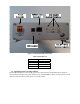
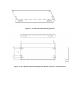
Table Of Contents
2.0 FIRST TIME SETUP
This section guides you thorugh the process of setting up and configuring you ICO MCAP UE for the
first time. The steps presented should be followed in the given order.
2.1 UNPACKING
Unpack the UE and accessory package items.
• ICO MCAP User Equipment (UE) Trunk Mount Gateway (TMG)
• A package of three wire power cables (Red, Black and Yellow, 20 ft each)
• A package or 4 RF cables (15 ft each)
• Installation Manual (this document)
• A set of 2 mounting brackets
• Screws for mounting brackets
• Test Sim (already installed inside the TMG)
2.2 INSTALLATION – GENERAL
1. For ease of service, route the radio cables and power cables together.
2. Always disconnect the negative side of the vehicle battery prior to any electrical work
3. Use cable ties every 30-45cm (12-18”).
4. The TMG can be mounted in either the horizontal or veritical position in the trunk.
5. The main +12VDC power line should be connected directly to the vehicle battery (or 12VDC
power supply). If you must connect it to another circuit, ensure sufficient amperage is available.
In the case of lab bench installation, tie the +12VDC Power and Ignition Sense wires together on
the 12 VDC power source. See figure 12 below.
6. The ground line should be connected directly to the vehicle’s battery ground.
7. Install the TMD in a protected area inside the vehicle. Allow at least a one inch space around all
surfaces, except for the surface attached to the mounting brackets to provide adequate cooling.
Ensure the location is accessible for servicing.
8. The TMG is not waterproof.
9. Do not route the power cables outside the vehicle.
10. The RF cables to antenna can be routed outside vehicle.