
Installation Manual
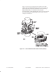
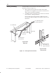
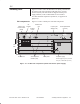
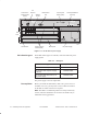
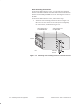
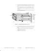
Table Of Contents

1027144–0001 Draft – Revision D.01
Installing indoor RT equipment 3–3
RT installation
Figures 3-2 and 3-3 show the RT indoor unit (IDU), which houses
the channel and control module (CCM) and service–specific
interfaces (SSIs). The IDU chassis is shipped with the power
supply installed, but the CCM and SSIs are not installed.
For IDU standards compliance information, see appendix B
(page B–3).
Figures 3-2 and 3-3 identify the main IDU components.
Figure 3-2 RT IDU main components (shown: IDU with ac power supply)
1
2
3
4
5
TM
BROADBAND
ENTER
RT CCM
rt018
Channel and
control module
(CCM)
Service-specific
interface (SSI)
Blank panel
Thumbscrew
AC power supply
Liquid crystal
display (LCD)
Control pushbuttons
(for LCD)
IFL
interface
Maintenance
port
SSI
slots
Power supply may be ac (as shown
here), dc, or dual mode (ac or dc).
Auxiliary
IF port
3.2
Installing IDUs
IDU components