
User's Manual
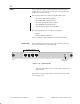
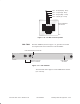
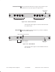
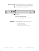
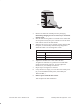
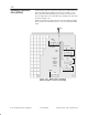
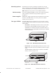
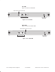
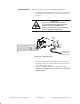
Table Of Contents

1027144–0001 Draft – Revision D.01
Installing indoor RT equipment 3–33
RT installation
hb060
3. Remove the SSI from its ESD protective packaging.
Retain the packaging in case it is necessary to return the
SSI for repair.
4. Slide the SSI into the guides on each side of the chassis SSI
slot and push it firmly into place until the front of the SSI is
flush with the front of the IDU chassis.
5. When the SSI receives power through contact with the IDU
backplane, it automatically initiates startup diagnostics.
Watch the LEDs to see the diagnostic results:
SSI LED indications:
Green SSI startup and normal operation
Red Failure
Flashing red TDM bus communication failure
6. Tighten the thumbscrews at each end of the SSI.
To tighten the thumbscrews, push them toward the IDU
chassis and turn them clockwise. To fully tighten the
thumbscrews, use a Phillips screwdriver.
7. Repeat steps 1 through 6 for each SSI.
8. If any SSI slots are empty, cover the slot with a blank panel.
(If you need additional blank panels, order HNS part
1026730–0001.)
9. Remove power from the IDU chassis.
This completes the IDU installation.