
User's Manual
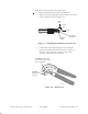

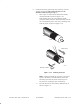
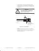
Table Of Contents
1027144–0001 Draft – Revision D.01Index-2
Crimp tool, 5–14
Customer equipment, connecting, 8–3
Customer sign–off, 8–3
D
Diagnostic mode, 6–37
Diameter of ODU mast, 4–5
Digital voltmeter, connecting to ODU, 7–6
Dismantling an RT, 10–16
Distance – RT to HT, 7–3
Documents, related, v
Drawings
hub network schematic, 2–1
hub rooftop drawing, 2–1
RT reference drawing, 1–2
DS3–ATM SSI, 6–26
DS3–TDM SSI, 6–25
DS3–Transparent SSI, 6–27
E
EIDU
installing, 6–31
mounting, 6–32
power supplies, 6–32
uses, 6–31
EIDU FEM, 6–32
Electronic serial number. See ESN
Element Management System. See EMS
Elevation
adjusting, 4–18
explained and illustrated, 4–18
Emissions, B–2, B–3
EMS, 2–6
database, 7–3
Equipment from other vendors, v
ESN, 7–3
location, 7–3
Existing structures as ODU mounts, 3–14
Exit (LCD), 6–38
Expansion IDU. See EIDU
F
F connector location for connecting voltmeter,
7–6
Failure indication on CCM LCD, 6–40
FCC, B–2, B–3
FEMs, 6–31
EIDU FEMs, 6–32
IDU FEMs, 6–32
installing, 6–34
types, 6–32
where installed, 6–32
Fiber extender modules. See FEMs
Front panel display. See LCD
G
Grounding
lightning arrestor, 5–22
ODU, 4–26
power supply
ac, 6–12
dc, 6–13, 6–18
dual ac or dc, 6–10
H
Handling materials, 3–5
Heat–shrink tubing (for IFL cable) , 5–10, 5–18
HT
acquisition, 7–10
ID, 7–10
Hub installation, v
I
IDU, 6–4
See also IDU chassis
components, 6–4
illustrated, 6–4
standards compliance, B–3
IDU chassis
See also IDU
connecting the IFL, 6–30
dc
circuit breaker, 6–19
disconnect device, 6–19
power–off circuit, 6–19
power–on test, 6–21
powering off, 6–18
Install mode, 7–4