
User's Manual
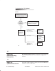
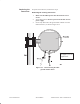
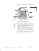
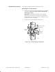
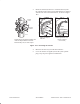
Table Of Contents

1027144–0001 Draft – Revision D.01 Maintenance 10–5RT installation
4. Loosen the four transceiver mounting bolts (shown in figure
10-2).
Figure 10-2 Removing the transceiver
Graphic to be
updated.
5. Rotate the transceiver until the bolts slide out of the four
grooves in the antenna bracket. (The direction of rotation
depends on the orientation of the antenna bracket—to the
right or left.) If the mounting bolts will not slide into the
grooves, loosen the bolts. See figure 10-2.
Important: A mechanical attenuator may be installed
(previously) in the antenna waveguide. If an attenuator is
installed, make sure it does not get lost or misplaced. Leave
the attenuator in the waveguide.
6. Cover the transceiver coupling (center hole) with a plastic
coupling plug (if available) or tape to prevent
contamination.