
User's Manual
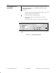
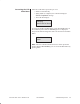
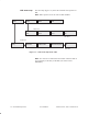
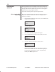
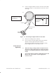
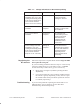
Table Of Contents

1027144–0001 Draft – Revision D.01 7–12 Commissioning the RT
RT installation
Table 7-1 Voltage indications for RT antenna pointing
Voltmeter reading Indication Corrective action
Current voltage level with
oscillation up to 4.1 V
. (The
reading intermittently peaks
at the current voltage level
for 2 seconds and then
rises to 4.1 V for 1 second.)
HT not acquired HT acquisition has not
occurred. Continue
pointing the antenna.
0.2 V to 3.9 V with no
oscillation
Correct HT
acquired
(Corrective action is not
required.) Continue with
the installation.
3.9 V to 4.1 V with no
oscillation
Correct HT
acquired
HT acquisition has
occurred but you must
install a mechanical
attenuator before
continuing with the
installation, refer to
section 6.10.
Current voltage level with
oscillation to 0 V.
(The
reading intermittently peaks
at the current voltage level
for 2 seconds and then
drops to 0 V for 1 second.)
Wrong HT
acquired
RT has been denied
acquisition by the wrong
HT. You must follow the
procedures listed in
Repointing the RT
antenna
below before
proceeding.
Follow the steps below to repoint the RT antenna only if the ODU
has acquired the wrong HT.
(If you successfully pointed the antenna in step 13—with a steady
voltmeter reading between 0.2 volts and 3.9 volts—you do not
need to follow steps 1 and 2 below; go on to section 7.5.)
1. Repeat steps 7 through 13 (voltmeter pointing and final
adjustments).
2. If you cannot obtain the correct voltmeter readings because
the antenna is grossly mispointed, you may have to repeat
the azimuth and elevation procedures explained in sections
6.7 and 6.8 (respectively).
If you encounter problems in pointing the antenna that are not
addressed above, refer to chapter 9. See the chart titled
Troubleshooting: RT antenna pointing.
Repointing the
RT antenna
Troubleshooting