
User's Manual
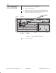
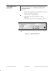
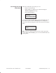
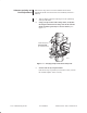
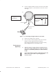
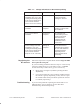
Table Of Contents

1027144–0001 Draft – Revision D.01
Commissioning the RT 7–11
RT installation
10. Connect a digital voltmeter to the F connector on the ODU,
as shown in figure 7-6, and select the 0 to 10 volt or 0 to 5
volt range.
Figure 7-6 Connecting the digital voltmeter to the ODU
Digital
voltmeter
Voltmeter connections
IFL
Ground wire
Use F connector to
connect cable to
pointing port.
Cap
rt057
BNC connector with
banana plug
Graphic to be
updated.
11. Observe the reading on the voltmeter.
12. Use a wrench to rotate the adjuster bolt on the azimuth
adjuster to slowly adjust the antenna azimuth.
Stop turning the adjuster bolt when you obtain a steady,
peak reading between 0.2 volts and 3.9 volts.
13. When the voltage reading remains steady between 0.2
volts and 3.9 volts, tighten the mast clamp nuts (shown
in figure 7-5) to 20 foot–pounds (27.1 Newton–meters)
torque.
If you cannot obtain a voltmeter reading between 0.2 volts
and 3.9 volts, refer to table 7-1 for the appropriate
corrective action.
Final antenna
tightening