
User's Manual
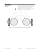
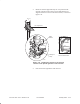
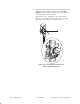
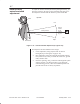
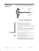
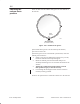
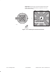
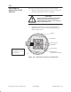
Table Of Contents

1027144–0001 Draft – Revision D.01
Installing ODUs 6–17
RT installation
To adjust the antenna elevation (upward or downward pointing
direction), you rotate the antenna upward or downward, as
illustrated in figure 6-15, until the elevation is set as desired.
rt053
Antenna
(front)
Side view
0elevation°
Downward
elevation
Upward
elevation
Figure 6-15 Antenna elevation adjustment
(upward or downward adjustment)
You adjust the antenna elevation in three stages:
1. Coarse adjustment, using only the built–in antenna
boresight (steps 1 through 4, on page 6–18)
2. Finer adjustment, using the boresight and elevation adjuster
tool (section 6.15)—after you attach the transceiver, ground
cable, and IFL cable.
3. Electronic pointing, using a voltmeter and integrated system
software (section 7.4). This procedure, a part of the RT
commissioning process, refines the elevation adjustment to
point the antenna as accurately as possible.
Obtain a coarse elevation adjustment as follows:
1. Using the boresight for reference, rotate the antenna until a
coarse alignment is obtained.
When the elevation is properly adjusted, you should be able
to see all of the HT in the boresight.
If the antenna does not rotate freely, loosen each of the
antenna bracket nuts slightly.
2. Finger tighten the reflector bracket locking nuts (again),
so the antenna is snug and without excess movement.
6.8
Initial (coarse)
antenna elevation
adjustment
Coarse elevation
adjustment