
User's Manual
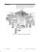
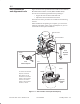
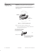

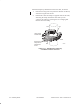
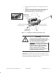
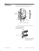
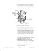
Table Of Contents

1027144–0001 Draft – Revision D.01
Installing ODUs 6–11
RT installation
2. Position the mast interface and permanent mast clamp on
opposite sides of the mast, with the interface on the same
side as the temporary collar, as shown in figure 6-9.
Allow the bottom surface of the mast interface to rest on the
top surface of the temporary installation collar.
Figure 6-9 Installing the antenna mount
hb068
Mast
Permanent
mast clamp
Mast
interface
Clamp nut
(1 of 4)
Swing clamp
toward interface.
Elevation
adjustment arm
Align the face of the mast
interface so that these two
surfaces are parallel.
3. Swing the clamp toward the interface until you can
“capture” the clamp by swiveling the free–swinging bolts
into the two slots in the clamp, as shown in figure 6-9.
The elevation adjustment arm (shown in figure 6-9) must be
behind the antenna (not installed yet). This means it will be
on the side of the interface that is farthest from the HT.
In some cases, to point the antenna in the right direction, it
is necessary to install the mount upside down, with the
elevation adjustment arm at the top of the mast interface.
This is acceptable, as long as the mount is installed so the
elevation adjustment arm will be behind the antenna.
4. Align the mast interface and temporary installation collar so
the rectangular face of the interface is parallel with the flat
surface of the collar, as shown in figure 6-9.
5. Finger tighten the four mast clamp nuts so the mast
interface and permanent mast clamp are snug and without
excess movement.
You should be able to smoothly pivot the mast interface and
mast clamp around the mast to permit coarse azimuth
adjustment.
(You fully tighten the mast clamp nuts later, after
completing all adjustments.)