
User's Manual
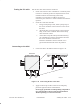
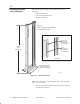
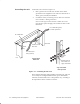
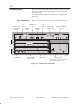
Table Of Contents

1027145–0001 Revision D Installing indoor hub equipment 6–7Hub installation
Figure 6-5 shows the HT IDU, which consists of the IDU chassis,
the channel and control module (CCM), and service–specific
interfaces (SSIs).
For IDU standards compliance information, see appendix B
(page B–3).
The main components of the IDU are identified in figure 6-5.
Figure 6-5 HT IDU main components
1
2
3
4
5
TM
BROADBAND
ENTER
HUB CCM
hb054
Channel and
control module
(CCM)
Service-specific
interface (SSI)
Blank panelThumbscrew DC power supply
Liquid crystal
display (LCD)
Control pushbuttons
(for LCD)
IFL
interface
Auxiliary
IF port
Reference
clock
LAN
interface
Maintenance
port
SSI
slots
Power supply may be ac, (as shown
here), or dual mode (ac or dc).
dc
6.2
Installing IDUs
IDU components