
User's Manual
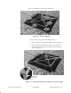
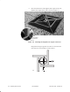
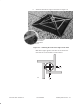
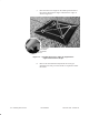
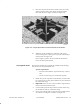
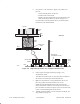
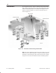
Table Of Contents
- Title page
- Contents
- About this manual
- Safety information
- Ch 1 - Installation summary
- Ch 2 - Prerequisites
- Ch 3 - Indoor equipment
- Ch 4 - Installing IFL cables
- Ch. 5 - Installing mast mounts
- Ch 6 - Installing ODUs
- Ch 7 - Commissioning the RT
- Ch 8 - Final steps
- Ch 9 - Troubleshooting
- Ch 10 - Maintenance
- App A - Acronyms
- App B - Standards compliance
- App C - Terminating the IFL cable
- Index

1027144–0001 Revision D
Installing mast mounts 5–5
RT installation
Figure 5-3 identifies the main mount components.
Figure 5-3 Mount components
Outer
base angle
Diagonal
base angle
Inner
brace angle
Mast
Mast
brace angle
rt015
Rubber
pad
• Follow steps 3 through 10 to assemble the mount.
3. Place the mount’s four outer base angles on the rubber pad.
4. Place the mount’s diagonal base angles on the rubber pad
and connect them to the outer base angles at the locations
circled in figure 5-4.
Figure 5-4 Connecting diagonal base angles to outer base angles
Carriage bolt
1
1
1
1
2
2
2
2
Flat washer
Lock washer
Hex nut
rt013