
User's Manual
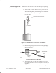
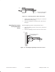
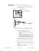
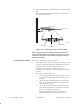
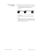
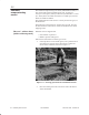
Table Of Contents
- Title page
- Contents
- About this manual
- Safety information
- Ch 1 - Installation summary
- Ch 2 - Prerequisites
- Ch 3 - Indoor equipment
- Ch 4 - Installing IFL cables
- Ch. 5 - Installing mast mounts
- Ch 6 - Installing ODUs
- Ch 7 - Commissioning the RT
- Ch 8 - Final steps
- Ch 9 - Troubleshooting
- Ch 10 - Maintenance
- App A - Acronyms
- App B - Standards compliance
- App C - Terminating the IFL cable
- Index

1027144–0001 Revision D 4–14 Installing IFL cables
RT installation
5. Connect the IFL cable to the RF arrestor, as shown in figure
4-11.
You connect the other end of the cable to the ODU later,
after you install the ODU.
Figure 4-11 Connecting the IFL to the RF arrestor
Ground wire
IFL
To ODU
N connector
RF arrestor
N connector
T0009013
Do not apply permanent weatherproofing until the RT has
been commissioned and tested. If the weather is wet or windy,
a temporary tape seal is recommended. Weatherproofing is
covered in section 8.1.
Test the IFL cable and connectors as follows:
1. Check each connector: Use a multimeter or continuity tester
to check for continuity (a short circuit) between the center
conductor and the connector body (outer shell).
If the meter or tester does not indicate an open (no
connection), the connector or cable is defective and must be
replaced.
2. Check the connectors and cable:
a. Using a small jumper cable, attach a jumper clip to
the center conductor of the connector on one end of
the cable.
b. Attach the other end of the jumper to the connector
body, so the center conductor and connector body
make electrical contact.
c. At the other end of the cable (at the IDU location),
use a multimeter to measure the resistance between
the center conductor and connector.
Resistance should be less than 10 ohms. If it is
greater than that find and correct the problem.
Testing the IFL cable