
User's Manual
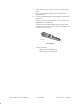
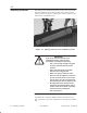
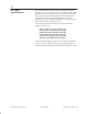
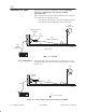
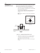
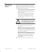
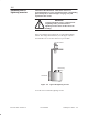
Table Of Contents
- Title page
- Contents
- About this manual
- Safety information
- Ch 1 - Installation summary
- Ch 2 - Prerequisites
- Ch 3 - Indoor equipment
- Ch 4 - Installing IFL cables
- Ch. 5 - Installing mast mounts
- Ch 6 - Installing ODUs
- Ch 7 - Commissioning the RT
- Ch 8 - Final steps
- Ch 9 - Troubleshooting
- Ch 10 - Maintenance
- App A - Acronyms
- App B - Standards compliance
- App C - Terminating the IFL cable
- Index

1027144–0001 Revision D 4–4 Installing IFL cables
RT installation
Figure 4-2 shows the IFL and lightning arrestor. A lightning
arrestor is required on the roof at the IFL building
penetration point.
Figure 4-2 shows how the IFL cable is installed in two segments
to accommodate the lightning arrestor:
• One segment from the IDU to the rooftop lightning arrestor
• One segment from the lightning arrestor to the ODU
ODU
(not installed yet)
T0009059
IFL
(cable
segment 1)
Roof
IDU
(Not to scale)
IFL
(cable segment 2)
Lightning arrestor
assembly
RF
arrestor
Figure 4-2 IFL plan
Because the IFL cable is installed in two segments, it is cut and
terminated (with an N–type connector) in four locations, as shown
in figure 4-3.
N
ODU
IFL
Lightning
arrestor
T0009002
IFL
Roof
IDU
N
N
N
N
= N connector location
Figure 4-3 Four locations where N connectors are installed
4.3
Overview: IFL plan
IFL connections