
User's Manual
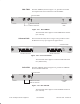
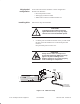
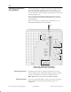
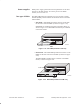
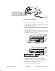
Table Of Contents
- Title page
- Contents
- About this manual
- Safety information
- Ch 1 - Installation summary
- Ch 2 - Prerequisites
- Ch 3 - Indoor equipment
- Ch 4 - Installing IFL cables
- Ch. 5 - Installing mast mounts
- Ch 6 - Installing ODUs
- Ch 7 - Commissioning the RT
- Ch 8 - Final steps
- Ch 9 - Troubleshooting
- Ch 10 - Maintenance
- App A - Acronyms
- App B - Standards compliance
- App C - Terminating the IFL cable
- Index

1027144–0001 Revision D
Installing indoor RT equipment 3–29
RT installation
The DS3–transparent SSI, shown in figure 3-20, supports an
unencumbered DS3 point–to–point service. The DS3 framing
structure, clocking, and control bits are transported without
visibility to the AIReach Broadband system.
Tx
ALARM
OK
Rx
TRNSP SSI3DS
OK
STATUS
ALARM
T0006023
BNC Rx connector
BNC Tx connector
Link status LEDs
SSI status
LEDs
Figure 3-20 DS3–transparent SSI
The maximum cable length for a DS3–transparent SSI is
450 feet (137.2 meters).
SSIs are installed in slots 2 through 5 in the RT IDU chassis and
are numbered SSI 1 through SSI 4, according to their positions in
the chassis:
Chassis slot SSI number
2 1
3 2
4 3
5 4
Slot 1 is occupied by the CCM.
LEDs on SSIs and fiber extender modules (FEMs) show:
• Module status (all SSIs and FEMs)
• Link status (if applicable)
• Line (or port) status (if applicable)
The subsections below show which LEDs are included on each
SSI or FEM and explain the meaning of the various LED on–off
conditions.
DS3–transparent
Numbering of chassis
slots and SSIs
SSI (and FEM) LEDs