
User's Manual
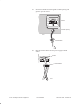
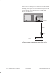
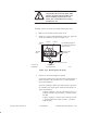
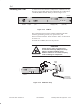
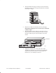
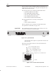
Table Of Contents
- Title page
- Contents
- About this manual
- Safety information
- Ch 1 - Installation summary
- Ch 2 - Prerequisites
- Ch 3 - Indoor equipment
- Ch 4 - Installing IFL cables
- Ch. 5 - Installing mast mounts
- Ch 6 - Installing ODUs
- Ch 7 - Commissioning the RT
- Ch 8 - Final steps
- Ch 9 - Troubleshooting
- Ch 10 - Maintenance
- App A - Acronyms
- App B - Standards compliance
- App C - Terminating the IFL cable
- Index

1027144–0001 Revision D
Installing indoor RT equipment 3–27
RT installation
Service–specific interface modules (SSIs) provide interfaces to
support specific network services. SSI types used depend on the
needs of the customer network.
The following SSIs can be installed in the RT IDU chassis:
• Quad–DS1 (HNS 1027070–0001)
• DS3–TDM (HNS 1027094–0001)
• Universal–DS1 (HNS 3003132–0001)
• DS3–ATM (HNS 3003136–0002)
• DS3–Transparent (HNS 1027094–0002)
The following RT SSIs are currently in development:
• MPEG
• Ethernet 10BaseT/100BaseT
SSIs are installed in slots 2 through 5 in the RT IDU chassis.
For explanation of SSI LEDs, see page 3–29.
The Quad–DS1 SSI, shown in figure 3-15, provides up to a four
T1 or E1 line link between the HT and RT.
QUAD DS1-SSI
OK
STATUS
ALARM
PORT 1 PORT 2 PORT 3 PORT 4
T0090038
SSI status
LEDs
RJ-48X connectors
Figure 3-15 Quad–DS1 SSI
The maximum cable length for a Quad–DS1 SSI is 655 feet
(199.6 meters).
Pinouts for the RJ–48X connectors on the Quad–DS1 SSI are
shown in figure 3-16.
Pin 1 - R1 signal (Ring - RX in)
Pin 2 - T1 signal (Tip - RX in)
Pin 4 - R signal (Ring - TX out)
Pin 5 - T signal (Tip - TX out)
Only pins 1, 2, 4, and 5 are used.
T0009040
1
2
4
5
Figure 3-16 RJ–48X connector pinouts
3.5
SSIs
Quad–DS1