
User's Manual
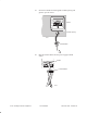
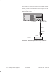
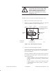
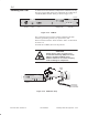
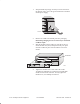
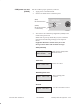
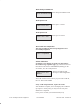
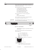
Table Of Contents
- Title page
- Contents
- About this manual
- Safety information
- Ch 1 - Installation summary
- Ch 2 - Prerequisites
- Ch 3 - Indoor equipment
- Ch 4 - Installing IFL cables
- Ch. 5 - Installing mast mounts
- Ch 6 - Installing ODUs
- Ch 7 - Commissioning the RT
- Ch 8 - Final steps
- Ch 9 - Troubleshooting
- Ch 10 - Maintenance
- App A - Acronyms
- App B - Standards compliance
- App C - Terminating the IFL cable
- Index

1027144–0001 Revision D
Installing indoor RT equipment 3–23
RT installation
A channel and control module (CCM) must be installed in the top
slot (slot 1) of the IDU chassis. For an RT IDU, the CCM must be
a CCM RT (HNS 1027181–0002), as shown in figure 3-13.
Liquid crystal
display (LCD)
Control pushbuttons
(for LCD)
IFL
interface
Maintenance
port
T0009046
Auxiliary
IF port
TM
BROADBAND
RT CCM
ENTERNEXT PREV
Figure 3-13 CCM RT
The CCM supports the interface modules installed in the IDU
chassis by performing control, bus, upconversion, and
downconversion functions. These modules—SSIs—are described
in section 3.5.
To install the CCM RT, follow the steps below:
CAUTION
Always wear a new or recently tested
electrostatic discharge (ESD) wrist strap
(figure 3-14) when handling circuit
modules. Failure to use a wrist strap may
result in damage to components.
TM
BROADBAND
ENTERPREVNEXT
T0009051
Wrist
strap
Connect to
IDU chassis
ground terminal.
Figure 3-14 ESD wrist strap
3.4
Installing the CCM