
User's Manual
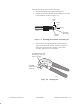
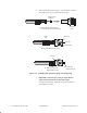
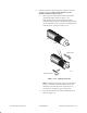
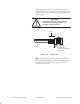
Table Of Contents
- Title page
- Contents
- About this manual
- Safety information
- Ch 1 - Installation summary
- Ch 2 - Prerequisites
- Ch 3 - Indoor equipment
- Ch 4 - Installing IFL cables
- Ch. 5 - Installing mast mounts
- Ch 6 - Installing ODUs
- Ch 7 - Commissioning the RT
- Ch 8 - Final steps
- Ch 9 - Troubleshooting
- Ch 10 - Maintenance
- App A - Acronyms
- App B - Standards compliance
- App C - Terminating the IFL cable
- Index
1027144–0001 Revision DIndex-4
LEDs
CCM, 3–25
FEMs, 3–29
SSIs, 3–29, 3–33
Lightning arrestor (for IFL), 4–4, 4–9
grounding, 4–12
Lightning protection, 6–25
Liquid crystal display. See LCD
Location
IDU, 3–4
ODU, 5–3
M
Main Menu (CCM LCD), 7–5
Maintenance, 10–1
Maps, local, requirements, 2–5
Mast
diameter, 6–4
horizontal, 6–2
Mast mount, 5–2
location, 5–3
standard type, 5–4
assembly instructions, 5–4
types, 5–3
using existing structures, 5–11
Materials
handling, 4–2
required for installation, 2–6
Mechanical attenuator, 7–12
entering the attenuator value, 7–13
installing, 6–19
replacing the antenna, 10–7
replacing tranceiver, 10–5
Menu map for CCM LCD, 7–6
Moisture contamination, 8–2
Mounts. See Mast mount and Antenna mount
Moving SSIs, 10–2
Multiple IFL cables, 4–11
N
N connectors
attaching to IFL cable, C–6
location (IFL cable), 4–4, C–1
National Electric Code (NEC), B–2
NEXT button (CCM), 7–7
Numbering
IDU chassis slots, 3–29, 7–15
SSIs, 3–29, 7–15
O
ODU, 6–1
connecting the IFL cable, 6–25
connecting voltmeter for antenna pointing,
7–10
frequency, selecting, 7–8
grounding, 6–23
illustration, 6–3
location, 2–1
replacing, 10–3
standards compliance, B–2
status, 7–16
transporting to the roof, 6–4
ODU location, 5–3
Operational state, 7–17
possible states, 7–17
Outdoor unit. See ODU
P
Penetrating the roof, 4–6
Penetration sleeve, 4–7
Personnel
number of installers, vii
qualifications, installers, vii
Pinouts, RJ–48X connectors on Quad–DS1 SSI,
3–27
Pointing the antenna, 7–8
fine adjustments, 7–9
initial (coarse) azimuth adjustment, 6–14
initial (coarse) elevation adjustment, 6–17
troubleshooting, 9–4
voltage indications, 7–11
voltmeter, 7–8