
User Manual


12
Assembly
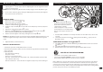
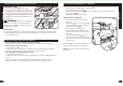
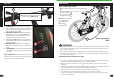
Handlebar and Stem Installation - Threadless Stem (as equipped):
CAUTION:
• Threadless Stem
B
should be
installed with bike sitting on the
ground and both wheels installed.
• Make sure Fork is fully inserted
from the bottom and Front Brake is
pointing FORWARDS.
• Disc Brake models: Disc Brake will
generally be on the LEFT side of the
Fork.
STEP 1:
1. Add Spacers
A
as needed for
proper Gap
E
.
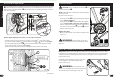
2. Insert the Stem
B
fully onto the
Fork Tube
C
.
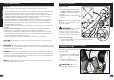
3. Point the Stem towards the front of
the bike and in line with the fork and
wheel.
4. With downward pressure on Stem,
move bicycle fork/wheel back and
forth so there is no looseness in
Headset Bearings
D
.
NOTE: Ensure there is BETWEEN 1mm
and 6mm gap between Fork Tube and
top of Stem
E
.
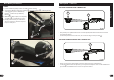
5. Place Cap
F
into stem and tighten screw securely
G
. Try to move
Fork back and forth. There should be no movement in Headset Bear-
ings
D
. If needed, redo above steps.
6. If supplied, insert Rubber Cap
I
securely.
STEP 2:
7. Tighten the stem bolts
H
securely.
WARNING: Ensure handlebar and fork turn left to right
smoothly and without friction.
1mm MIN
6mm MAX
G
F
A
B
H
E
C
A
D
I
29
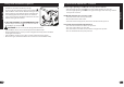
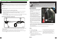
Disc Brake System Adjustment: (various models)
G
F
E
C
B
A
D
g A
BRAKE ADJUSTMENT (see g-A):
1. Loosen the Cable Clamp Bolt
A
.
2. Push the Brake Arm
B
toward the Adjusting Barrel
C
(this applies the brake).
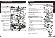
3. While holding the Brake Arm, pull the slack out of the Cable End
D
(through the Cable
Clamp) and tighten the Cable Clamp Bolt
A
.
WARNING: Do not over tighten the Cable Clamp. Over tightening the Cable
Clamp may cut the Cable and cause injury to the rider or to others.
4. Pull and release the brake lever several times to set the Brake Cable.
5. Spin the wheel. It should spin freely. If the Disc cannot spin freely in the Caliper, the
Cable might be too tight. Loosen the Cable Clamp Bolt and allow the brake arm to move
away from the adjusting barrel – repeat steps 1 through 4 until the wheel spins freely.
NOTE: An initial gap of 0.3mm (0.01 inch) is recommended.
6. A properly adjusted Caliper is set such that, the pads contact the Disc at approximately
1/3 lever travel and stops the disc at approximately 2/3 lever travel.
7. Minor adjustment can be made by turning the Adjusting Barrel on the brake lever or the
continued >>
NOTE: For Hydraulic Brakes, see Manufacturer’s instructions included with this product.
Maintenance