
User Manual

28
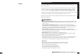
Tire and Tube Installation
A
B
1 2
3
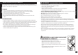
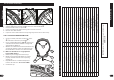
STEPS (start opposite Filler Valve):
1. Squeeze de ated tire inwards and insert Tire Lever under Tire Bead
A
.
2. Hook end of Tire Lever on a Spoke
B
.
3. Insert second Tire Lever and slide along rim to remove tire bead.
4. Remove Inner Tube and Tire.
5. Inspect for cause of at and remove any foreign object from the tire if necessary.
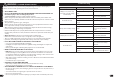
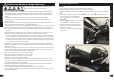
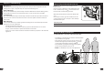
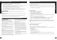
1. Using your hands, start with one Bead
A
of Tire
B
and install it all the way around Rim
C
.
2. Insert a slightly in ated Inner Tube
D
into the Tire
and make sure the Valve Stem
E
is straight and
aligned with the Rim Hole.
3. Work the second Tire Bead onto the Rim all the way
around. This will take a little more e ort than the
rst Tire Bead did. Use Tire Lever Tools if needed.
4. Make sure the Tube does not get pinched
between Rim and Tire.
5. In ate Tire just enough that it takes shape.
6. Double check that both Tire Beads are seated
properly and that the Valve Stem is pointing
straight out.
7. Fully in ate tube to recommended pressure
listed on Tire side wall - do not over-in ate.
8. Install Valve Cap.
STEP 1 REMOVE EXISTING TIRE AND TUBE:
STEP 2 INSTALLING NEW TIRE AND TUBE:
D
A
B
C
E
A
Maintenance
9
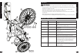
Parts Assembly
Parts Assembly List
No. Description No. Description
1 Frame 16 Seat Post
2 Stem 17 Seat Clamp
3 Battery Pack and Mount 18 Crank & Spindle Set
4 Fork 19 Pedal (Left & Right Set)
5 Front Wheel Assembly 20 Chain
6 Tire (x2) 21 Rear Derailleur
7 Tube (x2) 22 Front Fender and Hardware
8 Wheel Retainer (x2) 23 Rear Motor Wheel Assembly
9 Axle Nut (x4) 24 Rear Brake Disc/Caliper
10 Front Brake Disc/Caliper 25 Rear Sprocket Set
11 Grip Set 26 Front Light
12 Brake Hand Levers 27 Head Set Bearing
13 Right Shift Lever (styles may vary) 28 Headlight Switch Mount
14 Seat 29 Power Assist Switch
15 Seat Re ector 30 Rear Fender and Hardware
31 Chain Guard
32 Kickstand (not shown - styles vary)
NOTE: Models with Display please see included manual
KD58C-LCD