
User Manual


14
Assembly
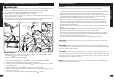
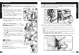
WARNING: To prevent the Seat coming loose and possible loss of control, the
“MIN-IN” (minimum insertion) mark
A
on the Seat Post must be BELOW the top of the
Seat Tube
B
.
STEP 1 INSERT SEAT POST INTO SEAT TUBE:
• If needed, loosen Seat Post Clamp Screw
D
or open
the Quick Release Lever
E
.
• Point the Seat forward and put the Seat Post
C
into
the Seat Tube
B
with the “MIN-IN” marks BELOW
the top of the Seat Tube as shown.
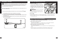
STEP 2 BOLT SEAT CLAMP: (various models)
• With Seat Post
C
inserted according to STEP 1 -
Tighten Screw
D
securely so Seat supports the
rider without moving.
STEP 3 QUICK RELEASE LEVER: (various models)
CAUTION: Operate the Quick Release Lever by HAND
ONLY DO NOT USE TOOLS.
1. As needed, open and close the Quick Release Lever
E
with one hand and tighten or loosen the Adjust-
ing Nut
G
by hand, so that you rst feel resistance
to the Quick Release Lever when it is in the “OPEN”
position
1
.
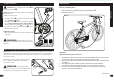
2. Push the Quick Release Lever to the “CLOSE” posi-
tion
2
- It will take strong force to clamp securely
so that the Quick Release Lever lays against the Seat
Post Clamp
F
.
WARNING: You must use strong force to
move the Quick Release Lever securely to the “CLOSE”
position
2
. This ensures that the seat does not move
during normal operation.
REFLECTOR: (as equipped)
Position Seat Post Re ector (if equipped)
H
so it points straight
backwards. Tighten Clamp Screw.
Seat Installation
A
A
G
1
2
3
1
2
C
B
C
F
C
E
H
D
23
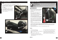
Operation
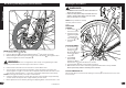
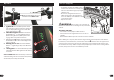
Rear Derailleur Adjustments
The rear derailleur has two adjusting screws. The “low” adjusting screw, sometimes
marked
L
, limits how far the rear derailleur and chain can move toward the wheel.
The “high” adjusting screw, sometimes marked
H
, limits how far the rear derailleur
and chain can move away from the wheel.
g C
1
2
3
4
5
6
B
A
Put the “high” adjusting screw in the correct position as follows (fi g D):
• Shift the chain onto the smallest rear sprocket. Loosen Nut
C
of the cable
clamp.
• Turn the lever Barrel Adjuster
A
and rear Derailleur Adjustor
B
all the way IN
(fi g C).
• Turn the “high” adjusting Screw
G
so the Jockey Roller
D
is in line with the
outside edge of the smallest rear Sprocket
E
.
• Remove the slack from the cable wire and tighten the Nut of the cable clamp.
D
E
F
C
G
H
g D
continued >>