
User Manual

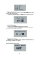
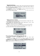
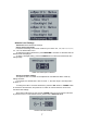
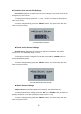
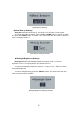
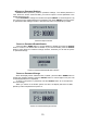
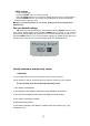
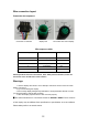
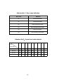
Table Of Contents
- Product name and Model
- Specifications
- Appearance and Size
- Function and Button Definition
- Install Instructions
- General Operation
- General Settings
- ◆Trip Distance Clearance
- ◆Unit Mile/KM toggling
- ◆Wheel Diameter Settings
- ◆Speed limit Settings
- ◆Battery Power bar Settings
- ◆Assist Level Settings
- ◆Controller Over-current Cut Settings
- ◆Power assist Sensor Settings
- ◆Speed Sensor Settings
- ◆Slow Start up Settings
- ◆Backlight Brightness Settings
- ◆Power-on Password Settings
- Power-on Password Enable/Disable
- Power-on Password Change
- ◆Exit settings
- Recover default settings
- Quality assurance and warranty scope:
- Warnings:
- Attached list 1: Error code definition
- Attached list 2:Assist level ratio defaults

12
Wire connection layout
Connector wire sequence
Connector to controller display end connection wire end to display
Wire sequence table
Wire sequence
Color
Function
1
Red(VCC)
+
2
Blue(K)
Lock
3
Black(GND)
-
4
Green(RX)
RX
5
Yellow(TX)
TX
■
Some products have wire connection with water-proof connectors, users can
not see the color of lead wires in the harness.
Warnings:
1.
Use the display with caution. Don’t attempt to release or link the connector when
battery is power on.
2.
Try to avoid hitting the display.
3.
Don’t modify display background parameters to avoid parameter disorder. Or else,
you will not be able to ride the bike normally.
4.
Have the display repaired when it does not work properly.
▉This manual instruction is a universal version for DISPLAY KD58C. Some versions
of this display may be different from specification to specification as to the software.
Please always refer to an actual version.