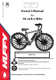
Date Code Label Here Owner’s Manual for 36-volt e-Bike © Copyright Huffy Corporation 2022 H-eBike-Comf EN 02-07-22 m0709 EN NOTE: Models with Display please see included manual KD58C-LCD This manual contains important safety, assembly, operation and maintenance information. Please read and fully understand this manual before operation. Save this manual for future reference. Always wear approved helmet and safety equipment when using this product.
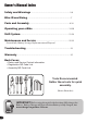
Owner’s Manual Index Safety and Warnings............................................................................................2-6 Bike ID and Sizing.......................................................................................................7 Parts and Assembly...............................................................................................8-18 Operating your e-Bike...................................................................................... 19-20 Shift System.........
MEANINGS OF WARNINGS: This symbol is important. See the word “CAUTION” or “WARNING” which follows it. The word “CAUTION” is before mechanical instructions. If you do not obey these instructions, mechanical damage or failure of a part of the bicycle can occur. The word “WARNING” is before personal safety instructions. If you do not obey these instructions, injury to the rider or to others can occur.
Warnings and Safety WARNING - TO AVOID SERIOUS INJURY: Failure of the rider to obey the following Safety Warnings can result in serious injury or death. Check local laws governing the use of electrical vehicles. • ADULT RIDERS ONLY. • SUPERVISION NECESSARY WHEN USED NEAR CHILDREN. • DO NOT USE THE VEHICLE IN AN UNSAFE MANNER OR AT AN UNSAFE SPEED. Not intended for jumps - this can damage the product. • CHOKING HAZARD: Small parts, adult assembly required.
• • • • • • • • • • • • Do not carry any items or attach anything to your bicycle that could hinder your vision, hearing, or control. • Do not ride with both hands off the handlebar. • Do not tow or push the product. • Do not modify the product. • Replace worn or broken parts immediately with original equipment. • If anything does not operate properly, discontinue use. DO NOT TAMPER WITH THE ELECTRICAL SYSTEM: Doing so may create a short, causing the fuse to trip or other damage including fire.
Warnings and Safety Lithium-Ion Battery & charger Warnings: 6 The following safety hazards may result in serious injury or death to the user of the vehicle: • Battery Charger for Indoor use only. Use of a battery or charger other than the supplied rechargeable battery and charger may cause a fire or explosion. Only use the supplied rechargeable battery (or lead-acid or lithium suitable replacement) and charger with the vehicle.
Owner’s Bicycle Identification Record Write this number below to keep it for future reference. If the bicycle is stolen, give this number and a description of the bicycle to the police. This will help them find the bicycle. Introduction NOTE: This information is only available on the bicycle itself. Each bicycle has a Recovery Code stamped into the frame. The Recovery Code can be found on the bottom of the crank housing as shown.
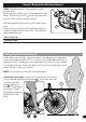
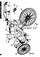
23 6 7 25 8 24 30 21 20 31 19 18 3 17 16 15 14 1 2 11 9 8 5 6 7 22 27 12 4 28 13 10 Parts Assembly 33 29
Frame Stem Battery Pack and Mount Fork Front Wheel Assembly Tire (x2) Tube (x2) Wheel Retainer (x2) Axle Nut (x4) Front Brake Disc/Caliper Grip Set Brake Hand Levers Right Shift Lever (styles may vary) Seat Seat Reflector 1 2 3 4 5 6 7 8 9 10 11 12 13 14 15 Chain Guard Kickstand (not shown - styles vary) 31 32 Parts Assembly Rear Fender and Hardware Power Assist Switch Headlight Switch Mount Head Set Bearing Front Light Rear Sprocket Set Rear Brake Disc/Caliper Rear M
Introduction Introduction to Assembly This Owner’s Manual may be made for several different style products. • Some illustrations may vary slightly from the actual product. • Follow instructions completely. • If the product has any parts that are not described in this manual, look for separate “Special Instructions” that are supplied with the unit. • All features, components and accessories are not included on all models. • Use the Index page to locate specific sections of this manual.
Installing the Front Wheel (light and fender optional) C G NOTE: If any hardware is already attached, remove and set aside. MOUNTING FENDER: 1. Insert Fender up into Fork as shown. 2. Install Front Light and Mounting Bolt through Fork and Fender Tab . 3. Install Nut securely. D Assembly WARNINGS: • Do NOT use Axle Nuts without serrations to attach the front wheel. • Failure to obey these steps can allow the front wheel to loosen while riding. This can cause injury to the rider or to others.
Handlebar and Stem Installation (various models) Assembly WARNINGS : • To prevent steering system damage and possible loss of control, the “MIN-IN” (minimum insertion) mark on the stem must be below the top of the Fork Locknut . • The Front Brake (if equipped) must be positioned in FRONT of the Fork. • Ensure the Fork is pointing FORWARD before proceeding. • Do not over tighten the stem bolt. Over tightening the stem bolt can damage the steering system and cause loss of control.
TO TEST THE TIGHTNESS OF THE STEM: • Straddle the front wheel between your legs. • Try to turn the front wheel by turning the handlebar . • If the handlebar and stem turn without turning the front wheel, realign the stem with the wheel and tighten the stem bolt(s) tighter than before (about 1/2 revolution only at a time) until the handlebar and stem do not turn without turning the front wheel. 1 TO TEST THE TIGHTNESS OF THE HANDLEBAR CLAMP: • Hold the bicycle stationary and try to move the ends of .
Seat Installation WARNING: To prevent the seat coming loose and possible loss of control, the “MIN-IN” (minimum insertion) mark on the seat post must be BELOW the top of the seat tube . Assembly A B STEP 1- INSERT SEAT POST INTO SEAT TUBE: • If needed, loosen seat post clamp screw or open the quick release lever . • Point the seat forward and put the seat post into the seat tube with the “MIN-IN” marks BELOW the top of the seat tube as shown.
Seat Bolt Saddle Adjustment (various models) A B B A A WARNING: Serrations on the mating C Assembly SINGLE BOLT CLAMP: 1. Loosen the clamp bolt sufficiently to allow any serrations on the mechanism to disengage before changing the saddle’s angle. 2. With serrations fully re-engaged and saddle in a comfortable riding position, tighten the clamp bolt securely to ensure the saddle will not come loose. surfaces of the clamp can wear with use and adjustment.
Pedal Installation Assembly CAUTION: There is a RIGHT pedal marked R and a LEFT pedal marked L. L NOTE: A Pedal Wrench is preferred for attaching Pedals. A thin open-end wrench can also be used. • The pedal marked R has right-hand threads. Tighten it in a clockwise direction. • The pedal marked L has left-hand threads. Tighten it in a counterclockwise direction (anti-clockwise).
Tires (as equipped) A Assembly MAINTENANCE: • Frequently check the tire inflation pressure because all tires lose air slowly over time. For extended storage, keep weight off of the tires. • Do not use unregulated air hoses to inflate the tire/tubes. An unregulated hose can suddenly over inflate tires and cause them to burst. • Replace worn tires. WARNING : Do not ride or sit on the unit if a tire is under inflated. This can damage the tire, inner tube and rim.
Drive Battery Installation STEPS: 1. Insert and turn Key fully Counter Clockwise before starting. 2. On bottom of Battery, align Slot and Plug with Tab and Pins and swing into place so that Battery slides into top of Battery Notch Mount . 3. With Battery fully in place, turn Key fully Clockwise to lock Battery in place. 4. Gently pull on battery to make sure it does not come lose. Remove key and keep in a safe place.
IMPORTANT! Before using the unit for the first time fully charge the Battery. Battery Charger will shut off when Battery is fully charged, but never charge longer than 12 hours. NOTE: Your e-Bike Li-Ion Battery can be charged either installed in the bike or removed. WARNINGS: A • All large Li-Ion batteries are a potential fire risk and should be charged in a safe place, preferably outside or in the middle of a garage floor. • Never charge a lithium battery unsupervised inside a house or building.
Operation C Operation D NOTE: Models with Display please see included manual KD58C-LCD 1. POWER ON: Press the Battery Power switch , the battery output is turned on and green and Red bars are displayed for about 5 seconds . 2. ENGAGE BATTERY ASSIST: Press the Green Thumb Button to engage Battery Assist. (Button will light Green). Battery Assist will engage after a few pedal revolutions. 3. With Green Thumb Button ON, press left Red Thumb Button to turn on Headlight. Press again to turn off. 4.
Shift System Parts of the Shift System: C A operates the Rear Derailleur B. Operation • Right-hand Shift Lever • Rear Sprocket Set . fig A A C B Operation: Operate the shift system as follows: 1. 2. 3. 4. 5.
Operation Shift System - continued CAUTION: Do not force the shift lever. Shift only when pedaling forward and without strong force. Do not backpedal. Backpedaling can cause the chain to come off the sprockets. Backpedaling and shifting while not pedaling can damage the sprockets and stretch the cable wire. There is no “correct gear” in which to ride the bicycle. The “correct gear” is the one that is comfortable to you. To select a gear while riding (this model has only one Front Sprocket 1. 2. 3. 4.
The rear derailleur has two adjusting screws. The “low” adjusting screw, sometimes marked L, limits how far the rear derailleur and chain can move toward the wheel. The “high” adjusting screw, sometimes marked H, limits how far the rear derailleur and chain can move away from the wheel. fig C 3 1 2 3 4 5 2 1 Operation Rear Derailleur Adjustments 6 A B Put the “high” adjusting screw in the correct position as follows (fig D): C B • Shift the chain onto the smallest rear sprocket.
Rear Derailleur Adjustments - continued Put the “low” adjusting Screw in the correct position as follows (fig E): • Shift the chain onto the largest rear Sprocket . • Loosen Nut of the cable clamp. • Turn the “low” adjusting Screw so the Jockey Roller is exactly below the largest rear sprocket. • Tighten the Nut of the cable clamp. Operation F H Adjust the Index Shift System: • Shift the chain onto the smallest rear sprocket. • Without turning the crank, turn the Right Shift Control one “click” rearward.
e-Bikes Maintenance: • Check the tightness of the fasteners before each use. Replace any fasteners that are damaged. • Inspect the product frequently. Failure to inspect the product and to make repairs or adjustments, as necessary, can result in injury to the rider or to others. Make sure all parts are correctly assembled and adjusted as written in this manual and any “Special Instructions.” • Immediately replace any damaged, missing, or badly worn parts.
Disc Brake System Adjustment: (various models) NOTE: For Hydraulic Brakes, see Manufacturer’s instructions included with this product. Maintenance fig A F G C E B A D BRAKE ADJUSTMENT (see fig-A): 1. Loosen the Cable Clamp Bolt . 2. Push the Brake Arm toward the Adjusting Barrel (this applies the brake). 3. While holding the Brake Arm, pull the slack out of the Cable End (through the Cable Clamp) and tighten the Cable Clamp Bolt . A B C D A WARNING: Do not over tighten the Cable Clamp.
Disc Brake System - continued 8. If you cannot reduce the gap by turning the Adjusting Barrel, the brake pads might be worn out and need to be replaced. Maintenance C Adjusting Barrel on the Caliper. Turn the Adjusting Barrel OUT to tighten the brakes or IN to loosen the brakes. NOTE: Make sure the Adjusting Barrel threads are fully engaged. Check adjustment again. PAD REPLACEMENT: 1. Remove the Caliper Mounting Bolts . 2. Remove the Caliper assembly . 3. Remove the Brake Pads from the Caliper. 4.
Tire and Tube Installation STEP 1 - REMOVE EXISTING TIRE AND TUBE: Maintenance 1 A 3 2 B STEPS (start opposite Filler Valve): 1. Squeeze deflated tire inwards and insert Tire Lever under Tire Bead . 2. Hook end of Tire Lever on a Spoke . 3. Insert second Tire Lever and slide along rim to remove tire bead. 4. Remove Inner Tube and Tire. 5. Inspect for cause of flat and remove any foreign object from the tire if necessary. A B STEP 2 - INSTALLING NEW TIRE AND TUBE: 1.
Lubrication Maintenance WARNING: • Do not over lubricate. If oil gets on the wheel rims or the brake shoes, it will reduce brake performance and a longer distance to stop the bicycle will be necessary. Injury to the rider or to others can occur. • The chain can throw excess oil onto the wheel rim. Wipe excess oil off the chain. • Keep all oil off the surfaces of the pedals where your feet rest. • Using soap and hot water, wash all oil off the wheel rims, the brake shoes, the pedals, and the tires.
Inspection of the Bearings Maintenance Maintenance: Frequently check the bearings of the bicycle. Have a bicycle service shop lubricate the bearings once a year or any time they do not pass the following tests: Headset Bearings: The fork should turn freely and smoothly at all times. With the front wheel off the ground, you should not be able to move the fork up, down, or side-to-side in the head tube.
Drive Battery Replacement 1. Insert and turn Key fully Counter Clockwise before starting. 2. Pull top of Battery to the LEFT and out to remove from Mount. 3. Remove new Battery from packing. Make sure no packing remains around Slot and Plug . 4. On bottom of Battery, align Slot and Plug with Tab and Pins on Battery Mount and swing into place so that Battery Notch slides into top of Battery Mount . 5. With Battery fully in place, turn Key fully Clockwise to lock Battery in place. 6.
Maintenance Lithium-Ion Battery Storage and Disposal Do not leave batteries unused for extended periods of time, either in the product or in storage. When a battery has been unused for 6 months, check the charge status and charge or dispose of the battery as appropriate. STORAGE: • • • • • • Charge or discharge the battery to approximately 50% of capacity before storage. Charge the battery to approximately 50% of capacity at least once every six months.
Troubleshooting Display is on, motor does not work or works slowly/ intermittently Reduced ride time Possible Cause Battery voltage is low Charge Battery Battery is loose in compartment Re-seat Battery Wire Harness connectors loose Check that Harness connectors are firmly attached Battery is low Recharge Battery does not hold a charge Replace Battery Battery at end of life Replace Battery Charger not connected Battery does not fully charge correctly Display does not turn on No Pedal assist
General: Part or model specifications are subject to change without notice. This Limited Warranty is the only warranty for the product. ALL WARRANTIES OTHER THAN STATED HEREIN ARE DISCLAIMED INCLUDING IMPLIED WARRANTIES OF MERCHANTABILITY AND FITNESS FOR A PARTICULAR PURPOSE, TO THE EXTENT ALLOWABLE BY APPLICABLE LAW. ALL LIABILITY FOR INCIDENTAL, PUNITIVE, SPECIAL, OR CONSEQUENTIAL DAMAGES ARE EXPRESSLY DISCLAIMED, TO THE EXTENT ALLOWABLE BY APPLICABLE LAW.
[ USA ] PLEASE - BEFORE RETURNING TO STORE: Contact Huffy Customer Service. We are glad to assist you with any parts or assembly problems you might have! For Fast Customer Service and email: www.huffybikes.com/contact To Order Parts: www.huffybikes.com/parts OR TEL: 1 800 872 2453 (US) [ CANADA ] PLEASE - BEFORE RETURNING TO STORE: Contact Huffy Customer Service.