Contents Product name and model............................................................................................................... 1 Specifications.................................................................................................................................... 1 Appearance and Size.......................................................................................................................1 Function and Button Definition................................................
Power-on Password Change.............................................................................................. 10 ◆ Exit settings............................................................................................................................ 10 Recover default settings............................................................................................................... 11 Quality assurance and warranty scope.......................................................................
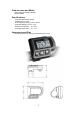
Product name and Model Electric Bicycle Intelligent Display, Model: KD58C.
Function and Button Definition ◆ Function Summary KD58C has a lot of functions to meet the riders’ needs. The indication elements are as follows: ● Battery SOC ● Assist level ● Speed indication (incl. Current speed, Max. speed and Avg. speed) ● Motor-output indicator ● Trip time ● Trip distance and Total distance ● The push-assistance function ● Switch the Lighting On/Off ● Error Code indication ● Various Parameters Settings (e.g.
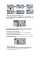
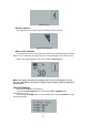
Display indication cycle interface ◆ Switching Push-assistance Mode On/Off To activate the push-assistance function, press and hold the DOWN button. After 2 seconds, the E-bike will go on at a uniform speed of 6 Km/h and “P” is shown on the screen at the same time. The push-assistance function is switched off as soon as you release the DOWN button. Push-assistance Mode ■ Push-assistance function may only be used when pushing the E-bike.
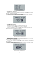
Assist Level “4” ◆ Power Indicator The output power of the motor can be indicated by below interface. Motor Power Interface ◆ Error code Indication The components of the E-bike system are continuously and automatically monitored. When an error is detected, the respective error code is indicated in text indication area. Refer to the detailed definition of the error codes in Attached list 1. Error Code Indication ■ Have the display inspected and repaired when an error code appears.
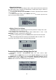
General Settings interface ◆ Trip Distance Clearance Clear Trip means trip distance clearance. Press the UP or DOWN button to choose YES or NO. The default value is NO. To clear a trip, choose YES and press the ON/OFF button to confirm. The screen says 'OK' and returns to the General Settings interface. Trip distance clearance ◆ Unit Mile/KM toggling Set Unit represents unit settings. The default value is Metric ‘KM’ To toggle unit, press UP/DOWN until the desired unit is displayed.
◆ Speed limit Settings Set LS represents speed limit settings. When current speed is faster than speed limit, the E-bike system will be switched off automatically. Limited speed range is 12Km/h to 40Km/h. The default value is 25Km/h. To change basic settings, press UP/DOWN to increase or decrease until the desired value is displayed. To store a changed setting, press ON/OFF button and the screen says 'OK' then returns to General settings interface.
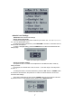
Personalized parameter settings Interface ◆ Assist Level Settings Power Set means assist level settings Power assist Level mode In assist level settings, there are 8 modes for your choice: 0-3, 1-3, 0-5, 1-5, 0-7, 1-7, 0-9 , 1-9. The default value is 0-5. To select the mode of assist level, press UP/DOWN to increase or decrease until the desired mode is displayed. To store a changed setting, press the ON/OFF button and access assist level ratio settings page.
◆ Controller Over-current Cut Settings Current Set represents controller over-current cut settings. The current value can be changed from 7.0A to 25.0A. To change basic settings, press the “+” or the “-” button to increase or decrease the value of the current. To store a changed setting, press the “ON/OFF” button. The screen says “OK” and returns to previous menu. Current Settings Interface ◆ Power assist Sensor Settings ‘Assistant num’ represents the numbers of magnets on PAS disk.
Speed Sensor Settings ◆ Slow Start up Settings Slow Start represents slow start up. The range is 1-4 seconds. 4 is the slowest. To change slow start up settings, press the UP or DOWN button to change the value and press the ON/OFF button to confirm. The screen says 'OK' and return to previous menu. The default value is 1. Slow Start up settings interface ◆ Backlight Brightness Settings Backlight Set represents backlight brightness settings. Level “1” is the low brightness, Level “3” is high brightness.
◆ Power-on Password Settings Password Set represents power-on password settings. The default password is 1212. When the screen shows P2:0000, you need to input the current password or the default password”1212”. Press UP/DOWN to change the numbers and press ON/OFF to confirm digits one by one until the correct 4-digit password is completed. Then press ON/OFF to access poweron password enable settings interface; otherwise stay still in the password input state.
◆ Exit settings In the settings state, Press the ON/OFF button to confirm the input. Hold the ON/OFF button for 2s to save the settings and then exit the current settings. Hold the DOWN button for 2s to cancel the operating but not to store the settings, and then return to previous menu. ■ If there is not any operations in one minute, display will exit the settings state automatically. Recover default settings dEF means recover default settings.
Wire connection layout Connector wire sequence Connector to controller display end connection wire end to display Wire sequence table Wire sequence Color Function 1 Red(VCC) 2 Blue(K) 3 Black(GND) - 4 Green(RX) RX 5 Yellow(TX) TX + Lock ■ Some products have wire connection with water-proof connectors, users can not see the color of lead wires in the harness. Warnings: 1. Use the display with caution. Don’t attempt to release or link the connector when battery is power on. 2.
Attached list 1: Error code definition Error Code Definition 21 Current Abnormality 22 Throttle Abnormality 23 Motor Phase Abnormality 24 Motor Hall Signal Abnormality 25 Brake Abnormality 30 Communication Abnormality Attached list 2:Assist level ratio defaults Level PAS 1 2 3 4 5 6 7 8 9 level mode 0-3/1-3 50% 74% 92% — — — — — — 0-5/ 1-5 50% 61% 73% 85% 96% — — — — 0-7/ 1-7 40% 50% 60% 70% 80% 90% 96% — — 0-9/ 1-9 25% 34% 43% 52% 61% 70% 79% 88