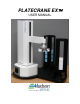
PLATECRANE EX USER MANUAL 10 Stern Avenue, Springfield, NJ 07081 Tel: 973-376-7400 Fax: 973-376-8265
Contents CHAPTER 1--Introduction ............................................................................................... 1 1. Overview ........................................................................................................................... 1 2. Computer Requirements ................................................................................................. 3 CHAPTER 2--Installation ..........................................................................................
5. Optional Components .................................................................................................... 31 CHAPTER 6--Hardware Specifications ......................................................................... 32 1. General ............................................................................................................................ 32 2. Robotic Arm...................................................................................................................
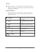
WARNING- - This product may be used only in the manner described in this manual. When used other than as specified, the safety protections provided by the equipment may be impaired. TABLE OF SYMBOLS: The following symbols are to alert your attention to important information or warnings that may present some hazards. These symbols may not appear in the manual or on the product. WARNING Possible hazardous situation could result in serious injury.
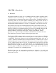
CHAPTER 1--Introduction 1. Overview The PlateCrane EX (See Figure 1) is a multifunctional Pick & Place instrument with a cylindrical robotic work envelope. It is designed to provide a simple answer to automating laboratory instruments that employ microtiter plates. The PlateCrane EX is a small and portable robotic system capable of handling up to thirty 96-well, 384-well or 1536-well microtiter plates per stack with a maximum capacity of 450 plates (15 stacks).
Figure 1 Teach Pendant Figure 2 PlateCrane EX User Manual Hudson Robotics, Inc.
2. Computer Requirements The following are recommended for proper operation of the PlateCrane EX and SoftLinx: Operating System: Windows XP SP3, Windows XP x64, Windows Vista 32, Windows Vista 64, Windows 7 32, Windows 7 64 2.5GHz Quad Core Pentium processor or faster, 4GB RAM or higher, CDRom drive, 2 available USB Ports 3GB MB of free disk space available .NET Framework 4.
Crane w/Stacks Figure 6 PlateCrane EX User Manual Hudson Robotics, Inc.
CHAPTER 2--Installation 1. Unpack the PlateCrane EX WARNING- - Power switch must be turned OFF during entire installation procedure DO NOT replace power cable with improperly rated cable DO NOT loosen or tighten any screws or touch parts not specified in the instructions Never force any component to fit The PlateCrane weighs 45 lbs. and should be lifted with two hands by the base; taking care to keep the PlateCrane upright. The arm should be turned to one side as not to swing while being moved.
Please refer to parts list to verify that all parts are included in the PlateCrane carton. If any parts are missing, please contact Hudson Robotics (see Chapter 7 for Technical Support). DO NOT DISCARD the PlateCrane carton. This carton has been specially created for this product and must be used for any additional shipping of the instrument to prevent damage. PlateCrane EX User Manual Hudson Robotics, Inc.
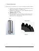
Optional- Teach Pendant Cable Power Cord Location Communication Cable location Figure 7 The Stacks can only be installed in one direction. The open side of the stack (Figure 8) needs to be facing the PlateCrane EX and the closed end must face the user (Figure 9). In Figure 10 you can see which way the stacks should be seated on the PlateCrane’s magazine base: with the “open” side facing inward, toward the PlateCrane. Figure 8 Figure 9 PlateCrane EX User Manual Hudson Robotics, Inc.
Stack installed correctly Figure 10 2.
3. Setting up the PlateCrane EX Remove PlateCrane EX from the carton and carefully remove the protective plastic covering. Unwrap Stack Base and place it near the PlateCrane. Remove the Stacks from the carton, then remove the stack from the packaging Install the supplied Stack and Alignment Base(s), by securing then to the crane base using the supplied screws. Adjust the leveling feet on the PlateCrane EX and Stack Base(s) as required by the surface that they are installed upon. 4.
0 – Power OFF position Fuse holder door Teach Pendant plug 1 – Power ON position Figure 11 6. Switching AC Line Voltage 110VAC/220VAC The power supplies installed in the unit are switching power supplies. That means they are able to handle both 110VAC and 220VAC without any changes to their configuration.
7. Installing PlateCrane Stacks: Note: Mishandling of plate stacks can result in misalignment. Unpack and unwrap the input/output stacks Mount the stacks onto the stack base by gently sliding them down onto the stack guide blocks. 8. Installing Barcode Scanner: If the Barcode Scanner option was purchased, position the scanner stand just outside the outer edge of the plate magazines, so that a plate's label can be scanned above the top of the stacks.
CHAPTER 3—PlateCrane EX Software 1. Brief Description of Software Hudson's standard PlateCrane application software (Software) can be found on one (1) installation CD. This CD can be loaded onto any PC running Windows XP SP3, Windows XP x64, Windows Vista 32, Windows Vista 64, Windows 7 32, Windows 7 64. This software provides a complete set of utilities to run the PlateCrane EX and any instrument interfaces purchased by the end user.
3. Manage Plug-Ins After SoftLinx is opened the instruments will need to have their correct communication ports associated to them. If an edgeport (USB-to-serial converter) was purchased this must be installed before the instruments are configured and ports assigned to them. To assign a communication port to an instrument you must click on the Manage Plug-ins button. This will open the Plug-in manger screen. From this screen you can add, remove, and edit Plug-ins that are installed on the computer.
Left click on the plug-in that you want to modify, once the plug-in is highlighted, left click the Configure Plug-in button. PlateCrane EX User Manual Hudson Robotics, Inc.
This will open the port setup screen for that particular interface. Under the available ports box, you will choose the correct communication port that the PlateCrane is connect to. Left click on the OK box to accept the changes of the communication port. Once you click ok, the window will close. and you will be brought back to the manage Plug-in screen. The Plug-in will now state that it is not initialized. To initialize the plugPlateCrane EX User Manual Hudson Robotics, Inc.
in left click on the initialize Plug-in button. If the instrument is installed on the correct communication port and the instrument is powered on then the status screen will then change to initialized. If the status comes back that it could not communicate with the firmware, then it is either attached to the wrong communication port or the instrument is not turned on. Once the PlateCrane is initialized successfully, then you can left click on the Plug-in setup button.
5. Calibration Screen PlateCrane Plug-in setup screen and the description of the buttons: PlateCrane EX User Manual Hudson Robotics, Inc.
Home- This button is used to home the entire PlateCrane. If the unit has not been homed the other buttons will be deactivated. Save- This button loads the points that you see on the screen to the PlateCrane memory. New Point- This button will add a new point that will either be a stack position, nest position, or an auxiliary position.
White Teach Block Access to all installed stacks and nests. PlateCrane installed. It must be leveled and powered on. 1. Turn SoftLinx on. Install the PlateCrane interface and access the PlateCrane setup screen. Ensure the PlateCrane and bases are level in relation to the desk surface it is sitting on. If the PlateCrane has stacks, remove all sleeves. PlateCrane EX User Manual Hudson Robotics, Inc.
2. Place the teach block onto the stack 1 position. 3. Using SoftLinx, open the setup screen for the PlateCrane. Click on New Point and choose new stack, OR edit Stack 1. 4. Put the crane into limp mode by pressing and holding the limp button on the Teach Pendant. The Teach Pendant will have a red LED light active once in limp mode. If the light does not activate, ensure the Teach Pendant is connected and reinitialize the crane via SoftLinx. PlateCrane EX User Manual Hudson Robotics, Inc.
5. Using your hands, while the crane is in limp mode, center the gripper over the teach block. The gripper may rest upon the white block. Look at the plate and gripper from directly above them to ensure they are roughly centered. 6. Once centered, press the “Teach Stack” icon, and then press Save Point at the bottom of the window to save the stack. NOTE – if there are no stacks, teach the most commonly visited nest as stack 1. Follow the instructions above.
PlateCrane EX User Manual Hudson Robotics, Inc.
9. Teach all nests. Place the white teach block in stack 1 or the common teach nest. Close gripper on the white teach block. Jog the crane in the +Z direction to travel height. Press and hold the Limp button on the teach pendant, then move the crane manually (grab the crane with your hands) with the teach block gripped into the nest. 10.
CHAPTER 4--Operation 1. Setting up the Workcell Once the PlateCrane and other instruments are configured with their correct communication ports, you can setup your workcell. When all the plug-ins are configured correctly left click the close button on the bottom right hand of the Plug-in Manager screen. This will bring you back to the main SoftLinx page where you have two options to choose from. The first is to open a new protocol and the second is to open an existing protocol. 2.
Once the workcell is defined follow the help tool, by left clicking on the help icon, to create your method or contact Hudson Robotics for technical support. 3. Setting up Plate Parameters Entering correct dimensions for the plates you will be using is critical for the proper handling of those plates by the PlateCrane, as it automatically adjusts its positions for each different plate-type used in every method based solely on the information entered into that plate’s definition.
The following ‘Initial Plate Locations’ form will be displayed: Click on the ‘Edit Definitions’ button to either change the parameters of a previously defined plate or to give you access to the ‘New Plate’ button. The ‘New Plate’ button is to create a new plate definition. Then, the following form will be displayed: PlateCrane EX User Manual Hudson Robotics, Inc.
You can select a pre-existing plate from Hudson’s library of plate types by selecting from a drop-down list in the ‘Choose a Defined Plate’ box at the top of the form, or simply enter or edit the other data fields manually. The five dimensional factors to be entered are defined as follows: Plate Height: The ‘stacking height’ of the plate when in one of the PlateCrane’s stacks. This is the distance from the bottom of the plate to the bottom of the plate immediately above it in the stack..
4. Plate Definitions Plate Height is illustrated in the following drawing: Plate Rise is illustrated in the following drawing: PlateCrane EX User Manual Hudson Robotics, Inc.
Lid Height and Lid Rise are illustrated in the following drawing: The check box labeled ‘Ignore “No Plate Present” Sensor’, if checked, will allow the PlateCrane to grip special plates that may be too narrow to grip without triggering the “No Plate Present” sensor in the gripper that normally would indicate an empty gripper. The text box labeled ‘StackLink Delay (msec)’ has no effect on PlateCrane operation. PlateCrane EX User Manual Hudson Robotics, Inc.
CHAPTER 5--PlateCrane Components 1. The Robotic Axes The PlateCrane has the following axes: 1. 2. 3. 4. R = rotates the PlateCrane horizontally Z = moves the PlateCrane arm vertically P = rotates the gripper horizontally Y= extends/retracts the PlateCrane arm The R-axis is driven by an encoded stepper motor. This axis has a rotational capability of 345. It utilizes a hard stop to prevent continuous rotation, and a proximity sensor, which determines the "Home" position for the horizontal rotation.
3. Power Cord/Communication Cable Connection The power cord plugs into the AC inlet on the rear of the PlateCrane. Input power is either 120V or 230V, 50 or 60 Hz. The communication cable is connected from the rear of the PlateCrane to the chosen serial port on the computer (usually COM 1). 4. Power Switch The power switch is located on the side plate with the power cord and communication cable (see Figure 11).
CHAPTER 6--Hardware Specifications 1. General Note: Specifications are subject to change without notice. Plate Capacity: Plate Format: Plate Storage Device: Housing Material: Gripper Material: Arm Mechanism: Standard-- Up to 30 plates without lids or 25 plates with lids. Additional-- Up to 420 plates without lids or up to 350 plates with lids. Portrait & Landscape - (Rotary Gripper) 2 removable stacks (expandable up to 15) Painted steel covering cast aluminum housing.
Home Position: Proximity Switch for rotary and vertical arm home (zero) ranging, with encoder homing pulse for final home position. Plate Present: Proximity switch Plate Sensor: Proximity Switch. 4. Dimensions Height: Weight: 28.5in. - 29.0in. (27.7in. w/out footpads) 45 lbs. 5. Electrical Power Input: Fuses: Grounding: Computer Interface: 100-240V~, 50/60Hz, 110VA For 120V / 230V Two 2A Time Delay, 5mm x 20mm (.205 in. x .787 in.
CHAPTER 7--Maintenance 1. Maintenance WARNING- - Qualified personnel can perform all maintenance procedures in this manual. Only Hudson representatives should perform any maintenance not discussed in this manual. Gloves should be worn during any cleaning procedure. 2. Cleaning the PlateCrane Note: DO NOT use/spray abrasive cleaners onto PlateCrane. Prior to cleaning, disconnect system power.
Remove the blown fuse. Replace it with the spare fuse. Slide the fuse holder tray back into the AC inlet until it clicks. Make sure when reinstalling the holder the AC line voltage reads the correct way on the inlet Reconnect the power cord to the PlateCrane and reconnect all other cables previously disconnected. Verify correct fuse replacement by turning the PlateCrane switch to ON position-the light will illuminate immediately.
CHAPTER 8--Troubleshooting For Troubleshooting Guide please contact Hudson Robotics. PlateCrane EX User Manual Hudson Robotics, Inc.
Warranty & Service Agreement Terms and Conditions 1. Warranty a. One-year coverage beginning on the factory ship date on all parts and labor including return shipping (to the customer) via UPS ground or equivalent. Warranty is limited to components and software purchased from or provided by Hudson Robotics, Inc. b.
2. Service Agreements I. Service Agreements, in one year periods, are available at prevailing rates and provide the following coverage in addition to the original warranty: a. One scheduled onsite maintenance service call per year of coverage to include evaluation and adjustment/repair to meet instrument performance specifications. b. Inspection and replacement of marginal components. c.
d. Warranty and service coverage does not include the following. Any service calls made as the result of the below shall be invoiced by Hudson Control at their standard rates including travel and labor expenses: 1. Damage caused by Customer misuse or operation outside of conditions prescribed in the Instruction Manual. 2. Damage caused by electrical surges or the use of improper sources, intervention of a third party, external influences such as fire, water damage, natural disaster, etc. 3.