Hudson Print and Apply USER MANUAL Rev 1.
Table of Contents CHAPTER 1 - Overview .................................................................................................... 2 A. System Requirements ............................................................................................. 2 B. Environmental Requirements ................................................................................ 2 CHAPTER 2 – Installation ................................................................................................ 3 A.
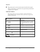
WARNING- - This product may be used only in the manner described in this manual. When used other than as specified, the safety protections provided by the equipment may be impaired. TABLE OF SYMBOLS: The following symbols are to alert your attention to important information or warnings that may present some hazards. These symbols may not appear in the manual or on the product. WARNING Possible hazardous situation could result in serious injury.
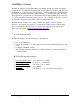
CHAPTER 1 - Overview The Print and Apply is an automated Barcode Labeling System. It creates and attaches printed labels to any SBS-standard microplate or microplate lid. The Print and Apply can apply labels any of the four sides of a microplate. The Print and Apply’s applicator head has 35mm of vertical travel which can hit anywhere on a standard microplate. The Print and Apply has an optional barcode scanner that can be mounted within range of the base, so you can print and confirm barcodes in one step.
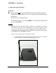
CHAPTER 2 – Installation A. Unpack the Print and Apply WARNING- - Power switch must be turned OFF during entire installation procedure. DO NOT loosen or tighten any screws or touch parts not specified in the instructions. Never force any component to fit. The Print and Apply system weighs 50 lbs. and should be handled with care to avoid mishaps. Overview: The Print and Apply will arrive in three separate boxes. The Zebra box contains the printer portion of the system.
2. Open the Hudson box and remove the applicator from the box, also remove any additional components from this box. Place the applicator on the table next to the alignment base. 3. You will now attach the applicator base to the alignment base. To do so, you will open the latches on the alignment base (See Figure 3). Then you will slide the alignment base into the cutout in the applicator base. You will now move the latches down until they meet the catches.
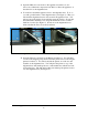
Printer Leveling Feet Figure 5 5. Attach all of the cables and accessories as shown in the following pictures, before turning the unit on. 1 2 3 1- USB Keyboard (optional) 3- Monitor Cable (optional) 2- Communication Cable for Applicator (Attach to computer) Print and Apply User Manual Hudson Robotics, Inc.
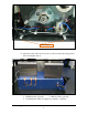
1 2 3 1 4 1234- Communication Cable to Rear of Printer Optional Barcode Cable Power Cable for Applicator USB cable for Printer (goes to computer) Print and Apply User Manual Hudson Robotics, Inc.
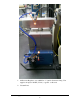
2 1 1- Air Pressure Regulator set to 60 PSI w/ ¼” Quick disconnect fitting. User supplies air input of 80 PSI (5.5 bar) or greater to this unit. 2- Vacuum Lines Print and Apply User Manual Hudson Robotics, Inc.
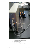
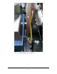
1 1. 1/8” Air Blast Tubing. (Color may vary.) Print and Apply User Manual Hudson Robotics, Inc.
NOTE: DO NOT DISCARD the Hudson or Zebra Printer box. These cartons have been specially created for these products and must be used for any additional shipping of the instruments to prevent damage.
B. Installing Media (Labels) After the PA1000 is setup correctly the media for the printer must be installed. 1. Open the front cover of the printer. Inside the printer wall is a schematic of how the media should run through the printer. Use this as a guide to position the media and print ribbon. 2. The print head must be lifted up so the print ribbon and media can go through the print head area. To lift up the print head slide the head bar labeled below counterclockwise until the head pops up.
3. Once the media and print ribbon are installed, slide the edge of the media backing between the air blast and strip bar. Once it is exposed below the air blast, pull enough media through so it is long enough to fit around the lower spindle. Tape the media to the lower spindle. 4. Once the media and ribbon are secured to the spindles, the print head can be lowered back into position and closed. After the print head is closed, the unit will be in a paused mode.
CHAPTER 3 - Calibration The Print and Apply is fully operational through SoftLinx V, with the Print and Apply interface. Codesoft 9.1 or greater must be installed prior to installing the Print and Apply interface. Refer to the SoftLinx V manual for general operation procedures and installation instructions for interfaces. A. Connection The Print and Apply works through an RS232 Serial connection. For computers that do not have serial ports, a USB to RS232 Serial connection will be required.
B. Setup Screen The unit requires setup in 3 steps to ensure successful use: Label Retrieval Setup: Calibration of how the unit picks up labels, which includes calibration of the vacuum and airblast, and position of the label head when retrieving a label. Apply Nest Setup: Calibration of the rotational nest on the applicator, as well as the position of the applicator head in relation to the nest when applying labels.
C. Hardware Setup Prior to Label Setup, the hardware must be configured to pick up labels properly. The apply head can be controlled from the label retrieval or apply head setup screens. 1. Move the apply head out of the way of the air blast. 2. Press the Feed button on the front of the printer to advance one label to the tear off position. Feed Button 3. The label should stop right at the edge of the strip bar as seen below. Strip Bar Air Blast 4.
6. Press the (Next-Save) button until the tear off setting is displayed, using the (+) and (–) buttons move the label until it is in the correct location. 7. Remove that label and press the feed button again 2-3 times to confirm the proper tear off location. 8. To save the tear off position press the (Setup-Exit) button, this will send it to the save options, the first option will be Save Permanently, press the (Next-Save) to accept the save command. 9.
D. Label Setup To calibrate the unit for label retrieval, the user must obtain vacuum cutoff values and teach the unit the location of the label retrieval point. The vacuum cutoff values are used for label detection during operation, and should be taught before teaching the label retrieval point. To obtain the correct vacuum cutoff values, the user must obtain a single label from the printer. Ensure that the air sources are properly attached to the unit at 60 psi.
Front Edge of tamp head Front edge or strip bar 0.030” Gap Once the head is over the label, press the “Save Point” button. It is highly recommended to test label retrieval now. Press the “Test Label Retrieval” button to test how it picks up a label. If it picks up a label within 2 seconds of its first attempt, it is taught properly.
E. Apply Nest Setup To teach the unit how to apply a label to the selected nest, the user must teach the unit the orientation of the nest by facing the side labeled “side 1” towards the body of the applicator. With standard Print and Apply Units, side 1 is the longest side of the nest that the colored corner, noted as A1, is touching. Other nest types that may be used will have additional documentation to note which side is A1.
Print and Apply User Manual Hudson Robotics, Inc.
CHAPTER 4 – Operation A. Creating Labels Codesoft v.9 is required to create labels. This section also assumes that the Zebra 110Xi4 printer is attached to the computer. Basic labels used with the Print and Apply are 2.5 inches wide by 0.25 inches tall. (63.5mm x 6.35mm) To create the label template, open Codesoft. Select New Label Document and ensure the label size has a 2.500 in. width and a 0.2500 in. height. Print and Apply User Manual Hudson Robotics, Inc.
To create a barcode, click on the barcode icon on the left toolbar (highlighted in the picture below) then click on the label itself. Print and Apply User Manual Hudson Robotics, Inc.
The barcode type, as well as attached counters can be modified on the screen below. Select a symbology that is compatible with the barcode scanner. Generally, the Code 39 and Code 128 barcodes are compatible. Print and Apply User Manual Hudson Robotics, Inc.
In addition, counter variables are used to automatically increment the barcode during operation. Please note – both the Shared box and ISO counter box MUST be checked to allow incrementing barcodes in SoftLinx. Once the label is set up, the user may print the barcode from Codesoft to ensure proper printing of the label. See Codesoft documentation or help files for more information. Print and Apply User Manual Hudson Robotics, Inc.
B. Setup and Testing Apply Profiles Apply profiles tell the unit how to apply a label to a specific plate type. The Apply Profile setup screen is available through the main Setup screen of the Print and Apply interface. To define an apply profile, the user must specify where to apply a label on each side of a specific plate, by specifying the apply height on each side. The Apply Height is the distance between the bottom of the plate and the bottom of the desired location of the label, in millimeters.
Print and Apply User Manual Hudson Robotics, Inc.
C. SoftLinx Operation The print and apply interface has two steps available in SoftLinx. The user may re-orient the rotational nest by selecting the “Move Applicator Nest” step. The main function of the Print and Apply is accessed by the “Print and Apply Label” step. This requires a Codesoft Label file and an Apply profile to be available. Previous sections of the manual note how to create both items required for functioning.
Print and Apply User Manual Hudson Robotics, Inc.
CHAPTER 5 - Maintenance A. Maintenance WARNING- - Qualified personnel can perform all maintenance procedures in this manual. Only Hudson representatives should perform any maintenance not discussed in this manual. Gloves should be worn during any cleaning procedure. B. Cleaning the Print and Apply Note: DO NOT use/spray abrasive cleaners onto Print and Apply applicator. Clean the outside surfaces of applicator using cloth or sponge dampened with alcohol or mild glass cleaner.
CHAPTER 6 - Warranty & Service Agreement Terms and Conditions A. Warranty a. One-year coverage beginning on the factory ship date on all parts and labor including return shipping (to the customer) via UPS ground or equivalent. Warranty is limited to components and software purchased from or provided by Hudson Robotics, Inc. b.
B. Service Agreements I. Service Agreements, in one year periods, are available at prevailing rates and provide the following coverage in addition to the original warranty: a. One scheduled onsite maintenance service call per year of coverage to include evaluation and adjustment/repair to meet instrument performance specifications. b. Inspection and replacement of marginal components. c.
d. Warranty and service coverage does not include the following. Any service calls made as the result of the below shall be invoiced by Hudson Control at their standard rates including travel and labor expenses: 1. Damage caused by Customer misuse or operation outside of conditions prescribed in the Instruction Manual. 2. Damage caused by electrical surges or the use of improper sources, intervention of a third party, external influences such as fire, water damage, natural disaster, etc. 3.