
User Guide
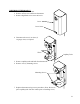
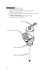
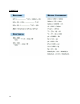


Table Of Contents
- ELECTRIC HEATER COMPANY
- WARNING / CAUTION
- TABLE OF CONTENTS
- GENERAL DESCRIPTION
- CONSTRUCTION
- OPTIONS
- Low Water Cut-Off
- Dial Temperature and Pressure Gauge
- Vacuum Relief Valve
- A vacuum relief valve may be provided with the unit to reduce the risk of back siphonage and back pressure of the system. The valve will be shipped loose for in-line installation. Instructions for installation are provided with the valve.
- Electro-Mechanical Timer
- An electro-mechanical 7-day time clock with battery back-up may be supplied for specific timing operations. A set of instructions will be supplied with the timer.
- FINAL CHECKS
- CONSTRUCTION
- GENERAL DESCRIPTION
- Symptom
21
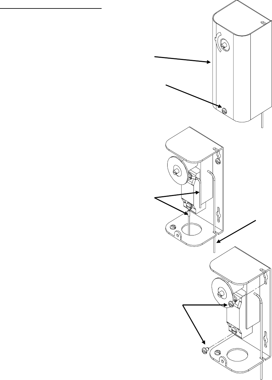
IMMERSION THERMOSTAT
1. Disconnect power from unit.
2. Remove access cover and locate thermostat.
3. Remove high limit cover screw and cover.
Cover
Cover Screw
4. Disconnect the two (2) or three (3)
14 gauge wires, as required.
Wires
Capillary Tube
5. Remove capillary tube and bulb from thermowell.
6. Remove two (2) mounting screws.
Mounting Screws
7. Replace thermostat using reverse procedure. (Note: Be sure to
place capillary tube into slot in base prior to installing cover.)