
User Guide


Table Of Contents
- ELECTRIC HEATER COMPANY
- WARNING / CAUTION
- TABLE OF CONTENTS
- GENERAL DESCRIPTION
- CONSTRUCTION
- OPTIONS
- Low Water Cut-Off
- Dial Temperature and Pressure Gauge
- Vacuum Relief Valve
- A vacuum relief valve may be provided with the unit to reduce the risk of back siphonage and back pressure of the system. The valve will be shipped loose for in-line installation. Instructions for installation are provided with the valve.
- Electro-Mechanical Timer
- An electro-mechanical 7-day time clock with battery back-up may be supplied for specific timing operations. A set of instructions will be supplied with the timer.
- FINAL CHECKS
- CONSTRUCTION
- GENERAL DESCRIPTION
- Symptom
15
SECTION V - SERVICING & REPLACEMENT OF PARTS
WARNING / CAUTION
Before servicing or replacing any part make sure to turn the power supply switch to the OFF position.
SURFACE TEMPERATURE HIGH LIMIT CUT-OFF
1. Disconnect power from unit.
2. Remove access cover.
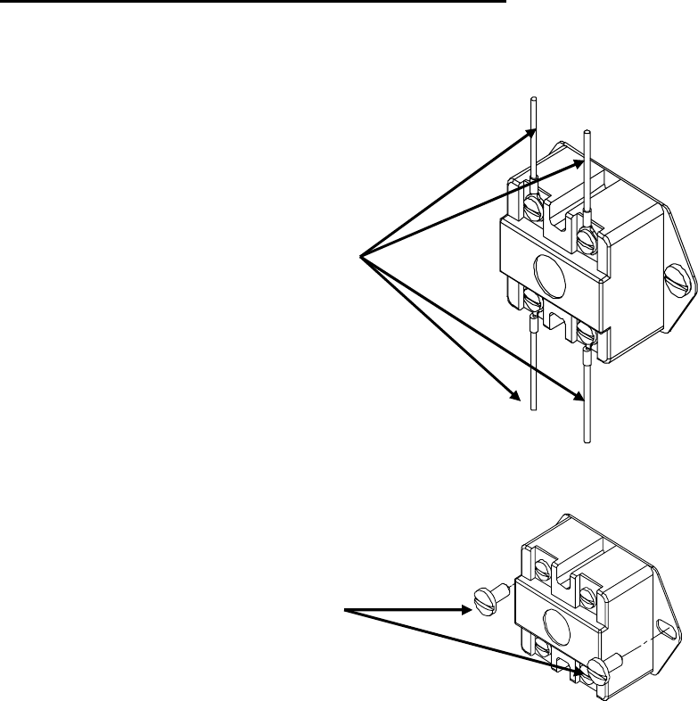
3. Disconnect the four (4) 14 gauge wires or three (3) 14 gauge wires and a jumper, as required.
Control Wires
4. Remove the two (2) mounting screws or disconnect from thermostat, as required.
5. Replace control and install new high limit switch by performing above steps in reverse order.
Mounting Screws