Hubbell Industrial Controls, Inc. A subsidiary of Hubbell Incorporated 4301 Cheyenne Drive Archdale, NC Telephone (336) 434-2800 FAX (336) 434-2803 Instruction Manual Transfer switches LX-440 Non-Automatic LX-450 Automatic 100, 200, 260, 400, 600, 800, 1000, 1250 Ampere 2, 3, 4 Pole Publication No.
Transfer Switch Table of Contents 1.0 Introduction....................................................................................................................................3 2.0 Specifications and Certifications ..................................................................................................4 Specifications .....................................................................................................................................4 Certifications ........................
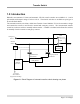
Transfer Switch 1.0 Introduction Hubbell’s non-automatic, LX-440, and automatic, LX-450, transfer switches are available in 2, 3, and 4 pole models with ampere ratings of 100 to 1250 A. The transfer switches are available as open type or in an individual cabinet. The automatic transfer switch has a Solid State Transfer Control Module, LX-301, that monitors voltage and controls the transfer to and from the normal and emergency sources.
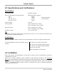
Transfer Switch 2.0 Specifications and Certifications Specifications Switch Mechanism Solenoid Actuation Short Circuit Ratings of Transfer Switches 100 A 200 A 260, 400, 600 A 800, 1000, 1250 A RMS Symmetrical Amperes 42,000 50,000 When protected by 65,000 a circuit breaker.
Transfer Switch Receiving and Storage After receiving the transfer switch inspect the cabinet for any damage that may have occurred during shipping. If the transfer switch is not installed immediately, cover the cabinet and store in a dry area. Condensation can corrode the contacts and other metal parts. Location The transfer switch should be located as close as possible to the engine generator or to the alternate power source.
Transfer Switch The Hubbell Transfer Control Module, LX-301, controls transfer to the emergency source and retransfer to the normal source. The LX-440 non-automatic transfer switch does not come with a Control Module. A selector switch initiates transfer and retransfer. Automatic Operation Transfer to Emergency Source The Control Module monitors the normal source phase voltage for acceptable limits of drop-out and pick-up.
Transfer Switch 5.0 Standard and Optional Features Standard Features The following standard features are provided with the LX-450 automatic transfer switch. Indicating lights NORMAL (PL1, Green) When the transfer switch is in the normal position (normal source contacts closed) auxiliary contact TSN-1NO closes to power the pilot light. EMERGENCY (PL2, Red) When the transfer switch is in the emergency position (emergency source contacts closed) auxiliary contact TSE-1NO closes to power the pilot light.
Transfer Switch Auxiliary Contacts Auxiliary contacts TSNa3, -a4 and TSEa3, -a4 are available for remote alarms, pilot lights, or other applications. These contacts are pre-wired for customer connections to PTB1-7 through PTB1-12. The contacts are rated at 10 A, 125/250 VAC. Manual Disconnect Switch The MDS (Manual Disconnect Switch) is mounted on the TRC board. This switch isolates the power source to the switching mechanism. Then the automatic transfer switch can only be operated manually with the handle.
Transfer Switch Plant Exerciser (B1–B2) The Plant Exerciser option is a seven-day clock that provides for automatic test operation of the generator set at pre-selected intervals. The clock is powered by a fused circuit from control transformer XFMR3. The Plant Exerciser option is used in conjunction with contacts to initiate engine starting without a load transfer, option B1. Option B2 includes a selector switch to simulate a power failure with or without a load transfer.
Transfer Switch 6.0 Maintenance DANGER: Do not touch the transfer switch until ALL power is disconnected. Shocks, burns, or death may result from high voltage. CAUTION: Only personnel who are familiar with the power distribution system and this manual should be allowed to inspect or perform maintenance on the transfer switch. Preventive maintenance The following checks should be preformed as part of routine maintenance: • A transfer test of the transfer switch should be preformed every week.
Transfer Switch Auto Test The following procedure is an example for testing the automatic transfer switch. A procedure should be written by qualified personnel that is applicable to the facility, the transfer switch options, and the power distribution system. Refer to job specifications for timing delays. CAUTION: Always close enclosure door when switch transfers with power connected. 1.
Transfer Switch Time Delay function NORMAL OVER-RIDE ON MONETARY OUTAGE RETRANSFER TO NORMAL ENGINE RUNNING UNLOADED EMERGENCY OVER-RIDE ON MOMENTARY OUTAGE TRANSFER TO EMERGENCY NEUTRAL POSITION TIME DELAY (optional) Frequency Monitor Typical factory setting Adjustment Range 1 second, engine generator 3 seconds, utility 30 minutes 5 minutes 1 second 0.5 to 6 seconds 2 seconds 3 seconds 0 seconds to 5 minutes 1 second to 10 minutes 60 Hz 30 to 100 Hz 2 to 30 minutes 2 to 30 minutes 0.
Transfer Switch Components 1. Transfer Control Relay Controls whether the automatic transfer switch is in the normal or the emergency position. De-energized - automatic transfer switch in Normal position Energized - automatic transfer switch in Emergency position 2. Timer circuit (not used on assembly –101 and -104) This circuit determines how long the automatic transfer switch stays in the neutral position. Jumper JMP1 selects one of four ranges. Potentiometer P1 adjusts the time within that range.
Transfer Switch 8.0 Plant Exerciser Timer Set the time 1) Press the Res.
Transfer Switch b) Press Prog. a second time to see the retransfer time. c) Press Prog.
Transfer Switch 9.0 Spare Parts and Drawing References The following lists contain part numbers and drawing numbers for identification and for ordering. If materials are needed from Hubbell, contact the local Hubbell representative to request the desired information or parts. Spare Parts Description Part No.