
User Guide


12
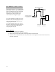
FOR REMOTE ON/OFF CONTROL
To remotely control the On / Off
operation of the heater, it is recommended
that a DPST switch or relay (by others) be
used to break both power legs (white and
black wires) connected to the top two
terminals of the J5 connector on the
control board. See diagram at right.
Use a NC (Normally Closed) relay to turn
the booster ON when energizing the relay
coil or to turn the booster OFF when de-
energizing the relay coil.
Use a NO (Normally Open) relay to turn
the booster OFF when energizing the relay
coil or to turn the booster ON when de-
energizing the relay coil.
FINAL CHECKS
1. Check all connections for tightness.
2. Ensure that all the above steps are completed.
3. Remove the protective outer plastic covering from the sheetmetal shell.
4. After the water is heated for the first time, monitor the water temperature as described in Section III,
Quarterly Inspection.
Wiring by
Customer
Remote Relay by Customer
1
2
3
4
Controller J5 Connector
Red Wire to
Contactor #2
Wiring from Contactor,
Power Distribution Block,
or Transformer
Yellow Wire to
Contactor #1