OPERATING AND MAINTENANCE MANUAL FOR COMMERCIAL ELECTRIC WATER HEATER ELECTRIC HEATER COMPANY BASE MODEL “ CE110 ”
HUBBELL ELECTRIC HEATER COMPANY P.O.BOX 288 STRATFORD, CT 06615 PHONE: (203) 378-2659 FAX: (203) 378-3593 INTERNET: http://www.hubbellheaters.com/ -- IMPORTANT -Always reference the full model number and serial number when calling the factory. The following information should be noted at time of installation and retained for future reference. Serial No.
WARNING / CAUTION 1. Please read all instructions prior to installing water heater. 2. Tank is to be completely filled with water and all air is to be vented before energizing. 3. Due to the rigors of transportation, all connections should be checked for tightness before heater is placed in operation. 4. Safety relief valve must be installed in tapping provided. 5.
TABLE OF CONTENTS SECTION 4 TITLE PAGE # I GENERAL INFORMATION 6 II INSTALLATION GUIDELINES 8 III SCHEDULED MAINTENANCE AND OPERATION 14 IV TROUBLESHOOTING 16 V SERVICING AND REPLACEMENT OF PARTS 17 VI WARRANTY 21
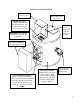
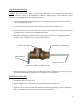
PARTS LOCATION DIAGRAM High Limit Access Cover Electrical Junction Box Cover High Limit Safety Switch - Manual reset switch designed to shut off all electrical circuits if water reaches 190°F Hot Water Outlet (Cold water inlet not shown on bottom). Thermostat - For constant temperature control. Factory set at 125°F. Thermostat and Heating Element Access Cover Long-Life Heating Element Waste is reduced with immersed heating element because all available heat passes directly into the water.
SECTION I - GENERAL INFORMATION GENERAL DESCRIPTION This book describes a packaged electric water heater that is a stationary, self-contained unit. The complete assembly consists of the storage tank, immersion electric heating element(s), thermostat, safety relief valve, safety high temperature cut out, and any other required electrical operating control. Optional equipment may be supplied with your unit. Please consult the product drawing for details specific to your assembly.
CONTROL THERMOSTAT The temperature of the water in the heater is regulated by the adjustable, automatic, immersion thermostat located behind the jacket front cover. This automatic control is set at the factory to maintain a water temperature of 125°F to reduce the risk of scald injury. The thermostat dial is graduated with markings form 1 to 10 with 10 being the hottest. Capillary Tube and Bulb OUTER SHELL AND INSULATION The tank is encapsulated in 1-inch thick fiberglass insulation.
SECTION II – INSTALLATION GUIDELINES WARNING / CAUTION DO NOT TURN ON THE ELECTRIC POWER SUPPLY to this equipment until heater is completely filled with water and all air has been released. If the heater is NOT filled with water when the power is turned on, the heating elements will burn out.
PIPING INSTALLATION NOTE: The most effective means for preventing deterioration from accelerated corrosion due to galvanic and stray current is the installation of dielectric fittings/unions. The installation of these fittings is the responsibility of the installing contractor. 1. Connect the cold water inlet and hot water outlet to the appropriate connections as shown; refer to installation diagram. 2. Provide a shut off valve in the cold water line. Mark for future emergency use 3.
ELECTRICAL INSTALLATION 1. Enter the electrical service entrance with properly sized feeder leads, conforming to the voltage stamped on the rating plate. Note: A separate fused branch circuit, conforming to local or National Electric Codes, must be provided by a qualified electrician. 2. Connect these power leads to wires enclosed in junction box with wire nuts. Refer to wiring diagram. CAUTION: There is a risk of electric shock in an ungrounded service.
Ground L1 L2 High Limit Cutout 1 2 3 4 Thermostat Capillary Tube Heating Element WIRING DIAGRAM 11
INSTALLATION WITHOUT TEMPERING VALVE Piping to Hot Water Support Bracket – (bottom bracket not shown) Temperature & Pressure Relief Valve Relief Valve Discharge Pipe Drain Valve Piping from Cold Water Air Gap Floor Drain 12
INSTALLATION WITH TEMPERING VALVE Piping to Hot Water Tempering Valve Support Bracket – (bottom bracket not shown) Piping from Cold Water Temperature & Pressure Relief Valve Drain Valve Air Gap Relief Valve Discharge Pipe Floor Drain 13
SECTION III - SCHEDULED MAINTENANCE AND OPERATION WARNING / CAUTION Before performing any maintenance procedure, make certain power supply is OFF and cannot accidentally be turned on. Exposure to 125°F or hotter water can cause scalding injuries. Appropriate caution must be taken when using hot water. Special supervision must be given to those who cannot react quickly such as children, invalids, or elderly persons. MAINTENANCE AND OPERATION The water heater is automatic in its operation.
ANNUAL INSPECTION 1. Flush tank as follows a. b. c. d. e. f. g. h. Shut off power supply. Attach a hose to the drain valve installed in the cold water piping. Close valve on the cold water line to the heater. Open the drain valve and direct the water to a drain. Open hot water faucet to admit air into the tank. Close drain valve and hot water faucet. Open valve on the cold water line to the heater. Turn power supply ON. LONG TERM SHUT DOWN 1.
SECTION IV – TROUBLESHOOTING Symptom No hot water Probable Cause Circuit breaker tripped at source. High limit switch tripped. Loose wires. Heating element inoperable. Low line voltage. Faulty thermostat. Water temperature below settings at all times Relief valve discharges continuously 16 Faulty thermostat. Excessive temperature or pressure in tank Corrective Action / Remedy Reset circuit breaker. Reset high limit switch. Tighten wires. Torque screws per torque chart included in Section VI.
SECTION V - SERVICING & REPLACEMENT OF PARTS WARNING / CAUTION Before servicing or replacing any part make sure to turn the power supply switch to the OFF position. SURFACE TEMPERATURE HIGH LIMIT CUT-OFF 1. Disconnect power from unit. 2. Remove access cover. 3. Disconnect the four (4) 14 gauge wires. Control Wires 4. Remove the two (2) mounting screws. Mounting Screws 5. Replace control and install new high limit switch by performing above steps in reverse order; refer to wiring diagram in Section II.
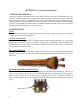
HEATING ELEMENT 1. Disconnect power from unit. 2. Shut off incoming water supply. 3. Attach hose to drain connection. 4. Lift manual release lever on relief valve to let air into system or break union on outgoing water line. 5. Drain water from tank. 6. Remove access cover. 7. Disconnect the wires from the heating element terminals. Thermowell Wires 8. Unscrew heating element. 9. Withdraw element assembly. Tank Coupling Element Assembly 10. Install Teflon tape and insert new heating element.
THERMOSTAT 1. Disconnect power from unit. 2. Remove access cover and locate thermostat. 3. Disconnect the two (2) control wires. Wires Capillary Tube 4. Remove capillary tube and bulb from thermowell in element. See previous page. 5. Remove mounting screw and knob. 6. Remove thermostat by sliding out from behind mounting bracket. Mounting Bracket Mounting Screw 7. Replace thermostat using the reverse procedure; refer to wiring diagram in Section II.
RELIEF VALVE 1. Disconnect power from unit. 2. Shut off incoming water supply. 3. Lift test lever on relief valve to relieve pressure in tank. 4. Disconnect overflow piping. 5. Unscrew relief valve, remove assembly and replace with new one. 6. Connect overflow piping. 7. Turn on incoming water supply and check for leaks. 8. Turn safety switch to ON position.
SECTION VI – WARRANTY LIMITED WARRANTY AND TANK REPLACEMENT POLICY The Electric Heater Co., (hereinafter called, the "Company"), offers the following warranty to the purchaser/owner of this electric water heater. Carefully read the entire warranty. Once you buy this product, the Company assumes you agree with the conditions and limitations of this warranty, and you accept the purchaser's/owner's responsibility for installation and care of the heater.
CONDITION AND LIMITATIONS Limited Warranty and tank Replacement Policy are valid only if you comply with the following conditions and limitations. It is not possible for the manufacturer to supervise the installation and use of this product. Therefore, it is a necessary and specific condition of this Limited Warranty and Tank Replacement Policy that the manufacturer relies on the diligence of the purchaser/owner in the installation and future use.