
Installation Instructions

3511B 06152020
72-00655
™
PRELIMINARY
3. Connect the ground wire attached to the NX Wall Station to the ground wired located in the gang box.
4. If you choose this method of installation, the 3M Command™ Strip is on not required. If direct mounting to a gang box use the longer 22mm screws
provided to mount the device directly to the gang box (See Figure 5).
5. Install a standard decora faceplate (not included) using the shorter 6mm screws provided to anchor the faceplate to the NX Wall Station.
CAUTION: the NX Wall Station faceplate provided is not intended for use when mounting directly to a gang box.
6. Turn the power ON at the service panel once installation is complete.
19
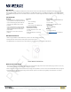
INSTALL INTO GANG BOX
• Turn OFF the power to the circuit you are working on at your
home’s breaker or fuse panel.
• Install the ground wire assembly onto the access door of the
Instant Switch.
FIGURE 4: GROUND WIRE INSTALLATION
23
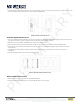
INSTALL INTO GANG BOX (CONT.)
• If you choose this method of installation, do not use the 3M
Command™ Strip on the back of the product. Instead, use the
longer, 22mm screws provided to mount it onto the gang box.
• Install a rocker switch faceplate (not included) using the shorter,
6mm screws provided to anchor the faceplate to the Instant Switch.
• Turn the power back ON at your circuit breaker.
FIGURE 5: DIRECT GANG BOX INSTALLATION
BATTERY REPLACEMENT
NOTE: The NX Wireless Rocker Wall Station uses a standard CR2032 battery ONLY, and has an expected lifetime up to 5 years under normal
operating conditions.
1. To access the battery rst remove the faceplate from the NX Wall Station.
2. After the faceplate has been removed press the module assembly as indicated in Figure 6 tilting the top toward you to remove the device from the
mounting plate.
25
BATTERY
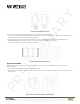
REPLACING BATTERY
• The iDevices Instant Switch uses a standard CR2032 battery ONLY,
and lasts up to 2 years.
• Access the battery by pressing the module assembly in where noted
and tilting the top toward you to remove from the mounting plate.
• After the module assembly has been removed, the battery will be
visible on the back.
•Removethebatterybyinsertingyourngerintothenotchand
pulling it toward you.
• When replacing the battery, be sure to install with the positive side
(+) facing out, so it is visible.
FIGURE 6: REMOVAL OF DEVICE FOR BATTERY REPLACEMENT
701 Millennium Blvd. | Greenville, SC 29607 | (864) 678-1000 | www.hubbellcontrolsolutions.com
Copyright © 2020 Hubbell Control Solutions, a division of Hubbell Lighting, Inc. All rights reserved. All product and company names, logos and product
identiers are trademarks ™ or registered trademarks ® of Hubbell Lighting, Inc. or their respective owners. Use of them does not necessarily imply any
aliation with or endorsement by such respective owners.