
Installation & Assembly


ASSEMBLY & INSTALLATION INSTRUCTIONS
Splash 3 Light Pendant 138913
A653
45148
3 OF 6
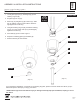
To Install Fixture (Figures 1 thru 2)
CAUTION: FAILURE TO INSTALL THIS FIXTURE PROPERLY MAY RESULT IN SERIOUS PERSONAL INJURY
OR DEATH AND PROPERTY DAMAGE. We recommend installation by a licensed electrician. This product must be
installed in accordance with applicable installation code(s), by a person familiar with the construction and operation of
the product and the hazards involved.*
Caution: Do not exceed maximum wattage noted on xture. Use only recommended bulbs with xture.
Please Note: After installation extra hardware and accessories are possible; our kits are used on multiple products.
CAUTION: BE SURE POWER IS OFF AT THE MAIN BREAKER BOX PRIOR TO INSTALLATION.
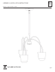
1. Carefully unpack xture (A) from the carton.
2. Thread jam nut (D) and crossbar (B) onto threaded nipple (I). Leave parts loose. Threaded nipple is attached to
canopy pipe assembly (G).
3. Using two machine screws (not provided), temporarily fasten crossbar (B) to the electric box.
Note: A new electric box comes with screws. When replacing a fixture, retain existing screws for use with new fixture.
4. Adjust length of threaded nipple (I) in crossbar (B) so canopy ring (F) will hold canopy (E) against the ceiling with no
threads showing for best appearance. When the correct adjustment is established, tighten jam nut (D) against cross-
bar to hold adjustment.
5. Remove crossbar (B) from electrical box and proceed with assembly instructions.
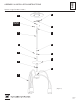
6. Locate fixture pipe (J) and slip it over the wires coming from fixture (A).
7. Apply a drop of the supplied thread locking compound to the internal threads of fixture coupling (H) and screw
fixture pipe (J) into fixture coupling, being careful not to twist the wires.
Note: Application of the thread locking compound is necessary to prevent the stem from loosening during
regular maintenance and cleaning of the fixture. Be certain to apply the compound.
8. Carefully slide canopy ring (F) and canopy (E) over xture pipe (J) until it rests on the xture (A). Make sure the
smaller diameter side of canopy ring is oriented up.
9. Slide the wires from xture pipe (J) through canopy pipe assembly (G).
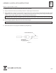
10. Unscrew clutch (K) from canopy pipe assembly (G); slide it across the wires and onto xture pipe (J). It may be nec-
essary to loosen set screw (L) in the clutch (K). Follow this with plastic sleeve (M), oriented so the tapered end nests
in clutch (K) (Figure 2).
11. Slide the xture pipe (J) into the canopy pipe assembly (G) as far as necessary to give you the total length of the x-
ture which you desire. Be careful not to scratch the pipe surface and to pull excess wire up through the canopy pipe
assembly (G). There must be a minimum 1-1/2" of inner pipe inside the outer pipe.
12. Thread clutch (K) back onto canopy pipe assembly.