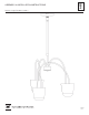
A653 ASSEMBLY & INSTALLATION INSTRUCTIONS Splash 3 Light Pendant 138913 45148 1 OF 6
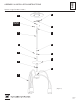
A653 ASSEMBLY & INSTALLATION INSTRUCTIONS Splash 3 Light Pendant 138913 Component Parts A Fixture B Crossbar C Ground Screw D Jam Nut E Canopy F Canopy Ring G Canopy Pipe Assembly H Fixture Coupling I Nipple J Fixture Pipe K Clutch L Set Screw M Plastic Sleeve N Glass (3) O Cups (3) P Retaining Ring (3) Q Retaining Ring Tool R Bulb (3) 45148 2 OF 6
A653 ASSEMBLY & INSTALLATION INSTRUCTIONS Splash 3 Light Pendant 138913 CAUTION: FAILURE TO INSTALL THIS FIXTURE PROPERLY MAY RESULT IN SERIOUS PERSONAL INJURY OR DEATH AND PROPERTY DAMAGE. We recommend installation by a licensed electrician. This product must be installed in accordance with applicable installation code(s), by a person familiar with the construction and operation of the product and the hazards involved.* Caution: Do not exceed maximum wattage noted on fixture.
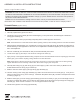
A653 ASSEMBLY & INSTALLATION INSTRUCTIONS Splash 3 Light Pendant 138913 13. Tighten set screw (L) in clutch (K) firmly with hex wrench provided. 14. Using two machine screws (not provided), fasten the crossbar (B) to the electric box. 15. Using suitable wire connectors (not provided) connect fixture wires to supply (white to white and black to black). Attach a pigtail lead to the crossbar ground screw (C).
A653 ASSEMBLY & INSTALLATION INSTRUCTIONS Splash 3 Light Pendant 138913 D B MACHINE SCREWS C G L J I M K E F H A (Figure 2) 45148 5 OF 6
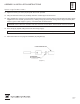
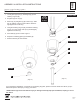
A653 ASSEMBLY & INSTALLATION INSTRUCTIONS Splash 3 Light Pendant 138913 To Install Glass and Bulb (Figures 3 & 4) 1. Locate glass (N) cups (O), retaining rings (P) and retaining ring tool (Q). 2. Set glass (N) into cup (O). 3. Raise cup (O) and glass up (N) to fixture (A). Slide the cup washer over the socket until the washer is tight against the socket ring. SOCKET RING VIEW BROKEN OUT FOR CLARITY SOCKET 4.