
Installation Instructions

HUBBARDTONFORGE.COM
-, -
154 RT. 30 SOUTH
•
CASTLETON, VERMONT 05735
32565A
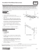
Assembly & Installation Instructions
If you need further assistance, or nd that you are missing any parts, please contact the dealer from which you purchased this product.
We hope you enjoy your xture!
* Hubbardton Forge will not be liable for injury or damage caused by improper installation, lamping or use of this xture.
A387
Planar Linear Pendant 139720D
Page 3 of 3
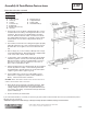
Install to Ceiling (Figure 5)
Component Parts
E Ceiling Bracket
G Clutch (2)
H Canopy
J Set Screw (2)
K Standoff (2)
L #10 Wood Screws (8)
M Hex Nut
1. Using wood screws (L) attach ceiling bracket (E) to a struc-
tural member in the ceiling, centering the bracket over the
outlet box. Wood screws are supplied with your xture;
however, different materials and/or construction methods
may require different fasteners. If in doubt, contact a quali-
ed electrician. Do not attach ceiling bracket directly to
outlet box.
2. Once xture is fastened to the ceiling and height is properly
adjusted, tighten the set screws (J) rmly with hex wrench
provided. Be sure to tighten set screws in both clutches
(G).
3. Raise Canopy (H). Connect Safety Cable (Q) from Canopy
to Mounting Bracket (E). Mounting bracket is shipped with
a nut on the stud to attach safety cable (Q).
4. To wire xture, route red and blue wires from canopy pipes
inward through the oval side slot in Mounting Bracket (E).
Blue and red wires on driver are shipped with connectors
attached. Connect wires from xture to connectors on
driver, red to red and blue to blue.
5. Attach a pigtail lead to the ceiling bracket (E) using cupped
washer (O) and hex nut (M). Connect xture ground wire
and pigtail lead to ground wire(s) from electrical box (bare
copper or green to bare copper or green).
6. Using suitable wire connectors (not provided) connect
xture wires to supply wires (white to white and black to
black). Push wires back into outlet box.
CAUTION: MAKE SURE WIRE CONNECTORS ARE TWISTED ON SE-
CURELY, AND NO BARE WIRE IS EXPOSED.
7. Barrel Knobs (N) are shipped on threaded studs (R). Slide
canopy (H) over Mounting Bracket (E) and push rmly to
ceiling, making sure that no wires are pinched between x-
ture canopy and ceiling. Screw barrel knobs (N) with studs
(R) into standoffs (K).
8. Restore electricity at main breaker.
K
E
O
M
R
(Figure 5)
L
H
Q
N Barrel Knobs (2)
O Cupped Washer
Q Safety Cable
R Threaded Stud (2)
N
J
G